Vacuum Generator, Multitasking / Manifold
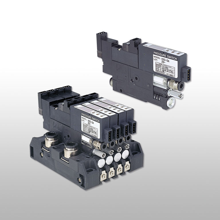
Multi-function vacuum generator module VX
The response characteristics of supply valve is maximized to realize a high-cycle vacuum system.
Options
-
No copper-based metallic material is used in flow paths
-
HNBR or FKM is used for the seal rubber material. *Some products are only compatible in the flow path.
Advantages
The response characteristics of supply valve is maximized to realize a high-cycle vacuum system.
A light weight and compact vacuum unit meeting market needs

There are 2 types of installation, direct-mounting by screw and DIN-rail mounting
Vacuum switch is available in three types.
Two types come with good visibility LED display, 2 switch-output and analog output+1 switch-output. Analog output type with no LED is also available as a low cost version.

Available in the specification for fields requiring "No copper-based metal material is used in airflow paths"and "Low-level Ozone resistance".
No copper-based metal material is used in airflow paths, and sealing rubber is designed to be resistant to low-level ozone.
Specifications
Common specification
| Fluid media | Air(JIS B 8392-1:Class1.2.1~ 2.4.3 compliant) |
|---|---|
| Operating pressure range | 0.3~0.7MPa |
| Operating temperature range | 5~50℃(No freezing) |
| Operating humidity range | 35~85%RH(No condensation) |
| Vibration/Impact resistance | Max. 50m/s2 / Max. 150m/s2 |
| Protective structure | Equivalent to IP40 |
| Lubrication | Not required |
| Pressure resistance(Air supply circuit) | 1.05MPa |
| Pressure resistance(Vacuum circuit) | 0.2MPa |
* Proof pressure does not indicate the pressure by which products operate normally but the pressure products does not break down.
Solenoid valve specification(DC24V)
| Rated voltage | DC24V ±10% |
|---|---|
| Power consumption | 1.2W(with LED) |
| Surge protection circuit | Varistor |
| Operation indicator light | Red LED is on when power is supplied |
| Manual override | Non-locking push type |
Solenoid valve specification(AC100V)
| Rated voltage | AC100V ±10% |
|---|---|
| Power consumption | 1.5VA(with LED) |
| Surge protection circuit | Diode bridge |
| Operation indicator light | Red LED is on when power is supplied |
| Manual override | Non-locking push type |
Valve specificatin for Ejector
| Operating system | Air-piloted |
|---|---|
| Valve | Normally closed |
| Response time(OFF→ON) | DC24V:7msec(-S3 model:8msec)/AC100V:10msec(-S3 model:11msec) |
| Response time(ON→OFF) | DC24V:14.5msec(-S3 model:23.5msec)/AC100V:16msec(-S3 model:29.5msec) |
| Valve | Double piloted(*1) |
| Response time(OFF→ON) | DC24V:8msec(-S3 model:6.5msec)/AC100V:11msec(-S3 model:9.5msec) |
| Response time(ON→OFF) | DC24V:23.5msec(-S3 model:18.5msec)/AC100V:29.5msec(-S3 model:15msec) |
*1) Shortest excitation time for solenoid valve is 50msec
*2) Response time is the value under the condition that supplied air pressure is 0.5MPa and rated voltage(100%) is applied
Valve specification for Blow-off
| Operating system | Direct-driven |
|---|---|
| Valve | Normally closed |
| Response time(OFF→ON) | 3.5msec(DC24V) / 8msec(AC100V) |
| Response time(ON→OFF) | 3msec(DC24V) / 14msec(AC100V) |
*) Response time is the value under the condition that supplied air pressure is 0.5MPa and rated voltage(100%) is applied
Vacuum filter specification
| Element material | PVF(Polyvinyl formal) |
|---|---|
| Filtration rating (*) | 5μm(Collection efficiency:95%) |
| Element surface area | 502mm2 |
*) According to our internal test
Blow-off function
| Blow-off air flow:Normally closed | 0~ 7.5L/min[ANR](When air supply is 0.5MPa) |
|---|---|
| Blow-off air flow:Double-piloted | 0.2~2L/min[ANR](When air supply is 0.5MPa) |
*) The value of blow-off air rate of normally closed type is for vacuum characteristic E10, stand-alone type. Blow-off air rate varies according to vacuum characteristic. Also, the blow-off air rate of manifold-type is 70% of the stand-alone type.
*2) In case of double-piloted type, the response time of blow-off air does not meet the one in the specification when the flow rate is outside the range mentioned above
*) Blow-off air flow varies depending on the vacuum port dia. and tubing length (pipe resistance and so on) on vacuum port side
Pressure sensor specification(DW:2 switch outputs with LED display)
| Current consumption | 40mA max. |
|---|---|
| Pressure sensitive element | Diffused semiconductor pressure sensor |
| Operating pressure range | -100~ 0kPa |
| Pressure setting range | -99~ 0kPa |
| Pressure proof | 0.2MPa |
| Rated voltage | DC12~24V ±10% Ripple(P-P) 10% max. |
| Output setting points | 2 |
| Repeatability | ±3%F.S. max.(at Ta=25℃) |
| Hysteresis | Lock(2%F.S.max.) |
| Switch output | NPN open collector(30V 80mA max./Residual voltage 0.8V max.) |
| Response | Approx. 2msec |
| Display | -99~0kPa(2-digit red LED display) |
| Display frequency | Approx. 4 times/sec |
| Display accuracy | ±3%F.S. ±2 digit |
| Resolution | 1 digit |
| Switch operation indicator lamp | SW1:Red LED lights when output is ON / SW2:Green LED lights when output is ON |
*) Allowable variation range of "Zero point voltage", "Span voltage" and "Switch output setting point" when pressure is applied repeatedly should be ±3%F.S.
Pressure sensor specification(DA:1 switch output & 1 analog output)
| Current consumption | 40mA max. |
|---|---|
| Pressure sensitive element | Diffused semiconductor pressure sensor |
| Operating pressure range | -100~0kPa |
| Pressure setting range | -99~0kPa |
| Pressure proof | 0.2MPa |
| Rated voltage | DC12~24V ±10%, Ripple(P-P)10% max. |
| Output setting point | 1 |
| Repeatability | ±3%F.S.max.(at Ta=25℃) |
| Hysteresis | Variable(Approx. 0~ 15%F.S.) |
| Switch output | NPN open collector(30V 80mA max./Residual voltage 0.8V max.) |
| Analog output/Output voltage | 1~5V |
| Analog output/Zero-point voltage | 1 ±0.1V |
| Analog output/Span voltage | 4 ±0.1V |
| Analog output/Output current | 1mA max.(Load resistance:5kΩmax.) |
| Analog output/Linearity | ±0.5%F.S. max.(at Ta=25℃) |
| Resonse | Approx. 2msec |
| Display | -99~0kPa(2-digit red LED display) |
| Display frequency | Approx. 4 times/sec. |
| Display accuracy | ±3%F.S. ±2 digit |
| REsolution | 1 digit |
| Operation indicator lamp | Red LED lights when output is ON |
*) Allowable variation range of "Zero point voltage", "Span voltage" and "Switch output setting point" when pressure is applied repeatedly should be ±3%F.S.
Pressure sensor specification(A0:1 analog output)
| Current consumption | 15mA max. |
|---|---|
| Pressure sensing element | Diffused semiconductor pressure sensor |
| Operating pressure range | -100~0kPa |
| Pressure proof | 0.2MPa |
| Rated voltage | DC12~24V ±10% ripple(P-P)10% max. |
| Analog output/Output voltage | 1~5V |
| Analog output/Zero-point voltage | 1 ±0.1V |
| Analog output/Span voltage | 4 ±0.1V |
| Analog output/output current | 1mA max.(Load resistance:5kΩmin.) |
| Analog output/Linearity | ±0.5%F.S.max.(at Ta=25℃) |
*) Allowable variation range of "Zero point voltage", "Span voltage" and "Switch output setting point" when pressure is applied repeatedly should be ±3%F.S.
Port size
Vacuum port size
Air supply port size
Stand-alone type
| Metric size (mm) | φ4, φ6 |
|---|
Manifold type
| Metric size (mm) | φ4, φ6, φ8, φ10 |
|---|
Exhaust port tubing size
Stand-alone type
| Metric size (mm) | φ6 |
|---|
Manifold type
| Metric size (mm) | φ6, φ8, φ10 |
|---|
Vacuum Characteristic Graph


Ordering Information
Stand-alone type

Manifold type

Manifold-base alone

Vacuum generator unit for manifold mounting

Detailed Safety Instructions
Warning
1.When using double piloted valve type under a vibration, install the vacuum generaor placing the switchover valve (main valve) at a right angle to the direction of vibration
2.Tighten screws with appropriate tightening torque referring to the digital catalog. Improper tightening may cause an air leakage, a falling off of the product or damages to the product.
3.For the double-piloted valve type, the switchover valve is in the state of neutral when the supply of both pilot air to the switchover valve for vacuum generation is stopped, or at the beginning of use after shipment. When resupplying pilot air, be sure to input a signal to the pilot valve or manually operate to position the switching valve in the required state before using it
Frequently Asked Questions for Vacuum Generator, Multitasking / Manifold Series
VUS011-NW and FVXS-DW-1 are not the type of the product itself, but the type of "sensor" installed in the product. The official model code of the product is laser marked (or labeled) on the body. FVUS011-** is the sensor for Vacuum Generator VK, and FVXS-** is the sensor for Vacuum Generator VX (External Vacuum Controller VXP / VXPT).
The type of our vacuum generator complex type (External Vacuum Controller) starts with "V". (VG ..., VQ ... etc.)
The sensor model code may start with FV ... and may be written as [PRESSURE SWITCH].
The sensor model code is described only in the specifications with a sensor.
"Tube exhaust type" which does not exhaust air and installing a silencer are recommended.
However, be aware when smooth plumbing without resistance is not carried out such as with too long tube to exhaust, it becomes resistance to exhaust and impair the vacuum degree.
The vacuum characteristic of each type is different.
【H type】
High-vacuum type (Rated supply pressure* : 0.5Mpa)
【L type】
Large-flow type (Rated supply pressure* : 0.5Mpa)
【E type】
High-vacuum at low air pressure supply type (Rated supply pressure* : 0.35Mpa)
For high-vacuum, H type, to provide large-suction flow, L type, and to save supply air, E type is recommended respectively. (Details of final vacuum and suction flow are determined by choice of the nozzle diameter.
*)
What is rated supply pressure?
Rated supply pressure guarantees product performance under the designated conditions and is also the supply pressure, which a vacuum generator supplies, of basis to design and use. The ultimate vacuum reaches to the max. around the rated supply pressure value.
The following graph shows the case of H type. The ultimate vacuum is the highest near 0.5Mpa. (ex. Simple vacuum generator VHH07 (Nozzle dia. 07: ø0.7mm)
When the product performance is reduced, the followings can be the causes.
Please check the product in terms of these points.
1) Check the supply air
Please check if the supply air flow volume and the air pressure are sufficient.
2) Check the nozzle clogging
When foreign substances are clogged in the nozzle, do flushing to clean it.
3)Clogging of the vacuum filter on sucking side or the silencer on the exhaust side.
When a filter is clogged, replace it with new one.
Rated supply pressure of Vacuum Generator is designated according to the vacuum characteristics (H, L and E type) respectively.
This rated supply pressure is required air pressure to start operating Vacuum Generator. When the supply air pressure is under the rated supply pressure, abnormal sound may be caused by some particular supply pressure.
During abnormal sound is being generated, the vacuum characteristics may become unstable and cause troubles such as influencing pressure detection by a sensor. Reset the product to keep the supply pressure satisfying the rated supply pressure in that case. ( Product spec. is the value in operation of Vacuum Generator.)
Both types indicate the valve position when the valve is unactuated. (normal position).
Normally closed type (N. C.)
Normal position is closed, covering a valve . When the valve is actuated, or electricity flows, the valve opens.
Normally open type (N. O.)
Normal position is open, uncovering a valve. When the valve is actuated, or electricity flows, the valve closes.
With the valve unactuated, the entrance leads to the exit.
There are two ways of measuring pressure, absolute pressure and gauge pressure.
Absolute pressure
Absolute pressure is zero-referenced against a perfect vacuum.
It is commonly used to measure flow rate.
When indicated, "abs" is inserted following the unit, for example 10 kPa abs.
Gauge pressure
Gauge pressure is zero-referenced against ambient air pressure.
It indicate how much pressure per 1cm2 is against the ambient air pressure. It is commonly used for indication of manometer. When the pressure is over the ambient air pressure, it is called "positive pressure" and when it is under the ambient air pressure, it is called "negative pressure."
Inquiries about this product
It is also possible to suggest products suitable for various conditions such as applications and functions. Please feel free to contact us or visit the nearest sales office.
The following are frequently asked questions. Please check before making inquiries.
