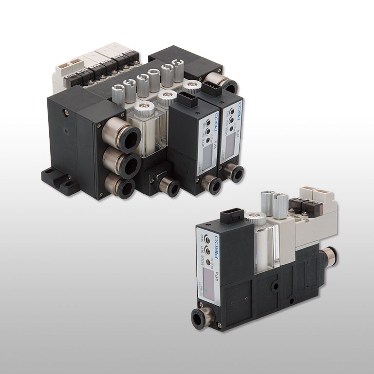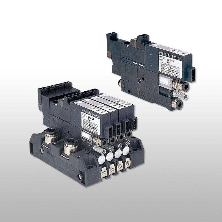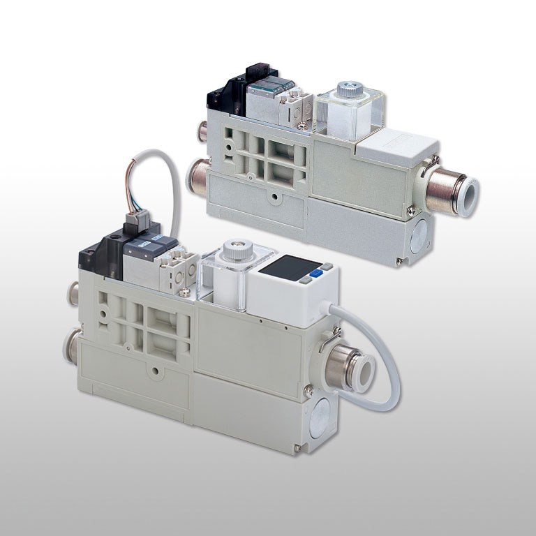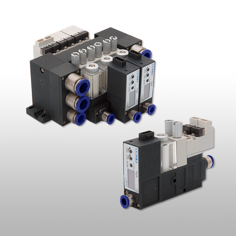
Vacuum Accessories
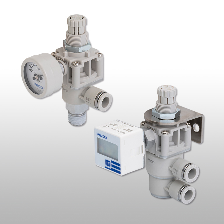
Vacuum Regulator Push-lock type
Not only source pressure, terminal pressure can be controlled. Push-lock knob for easy adjustment.
-
No copper-based metallic material is used in flow paths
-
HNBR or FKM is used for the seal rubber material. *Some products are only compatible in the flow path.
Advantages
Not only source pressure, terminal pressure can be controlled. Push-lock knob for easy adjustment.
Push-lock knob for easy pressure adjustment.

Realized max. 50% of weight saving compared to conventional model.
The main body is made of resin, and aluminum is used for the metal part.

Standard product equivalent to S3 specifications.
-S3 specification is available for fields requiring "No copper-based metal material is used in airflow paths" and "Low-level Ozone resistance". The rubber material is HNBR, which has excellent ozone resistance. (*) Gauges and sensors are excluded for S3 specifications.
The lead-out directions are free by rotating the fitting part individually.

Best suitable for the control of the source pressure. Terminal pressure also can be controlled.

Specifications
Specifications of Regulator Pressure indication code M, Blank, V4(P), V5(P)
| Fluid medium | Air |
|---|---|
| Operating pressure range | -100~100kPa/-100~0kPa(According to specifications of Pressure Gauge) |
| Setting Pressure range | -100~-1.3kPa |
| Max. suction flow rate | 30L/min[ANR] |
| Operating temp. range | 0~50℃/0~40℃(No freezing) (According to specifications of Pressure Gauge) |
* Please make sure that it changes depending on pressure of the vacuum source.
Specifications of Regulator Pressure indication code D
| Fluid medium | Air |
|---|---|
| Operating pressure range | -100~0kPa |
| Setting Pressure range | -100~-1.3kPa(*) |
| Max. suction flow rate | 30L/min[ANR] |
| Operating temp. range | 0~50℃(No freezing) |
* Please make sure that it changes depending on pressure of the vacuum source.
Specifications of Regulator Pressure indication code G
| Fluid medium | Air |
|---|---|
| Operating pressure range | -100~0kPa |
| Setting Pressure range | -100~-1.3kPa(*) |
| Max. suction flow rate | 30L/min[ANR] |
| Operating temp. range | 0~40℃(No freezing) |
* Please make sure that it changes depending on pressure of the vacuum source.
Specifications of φ30mm Negative Pressure Gauge
| Fluid medium | Air |
|---|---|
| Indicated pressure range | -100~0kPa |
| Pressure indication accuracy | ±5% F.S.(at 25℃) |
| Operating temp. range | 0~40℃(No freezing) |
Specification of Digital pressure gauge
| Rated pressure range | -101~0kPa |
|---|---|
| Indicated pressure range | -101~10kPa(*1) |
| Proof pressure | 300kPa |
| Fluid medium | Air, Non-corrosive / Non-flammable gas |
| Battery | CR2032 Lithium battery |
| Battery life | About 3 years (Display turn on 5 times/day) |
| Low-power indicator | Incorporated |
| Battery replaceability | Yes |
| Turn-on interval | Display turns off after 60sec. |
| Sampling rate | 2Hz(2times/sec.) |
| Repeatability | ≦±1% F.S. ± 1 digit |
| LCD display | 7segment, 3.5 digit |
| Indication accuracy | ±2% F.S. ± 1 digit or less (at Ta=25 ±3℃) |
| Protective structure | IP65(*2) |
| Ambient temp. range | Operation:0~50ºC, Storage:-10~60ºC(No dew condensation or freezing) |
| Ambient humidity range | Operation / Storage:35~85%RH (No dew condensation) |
| Vibration proof | Total amplitude1.5mm or 100m/s², 10Hz ~ 150Hz ~ 10Hz for 1min., 2 hours each direction X, Y, Z |
| Shock resistance | 100m/s2, 3 times each in direction X, Y, Z |
| Temperature characteristics | ±2%F.S. of detected pressure (at 25°C) |

Specifications of Pressure Sensor(Large digital pressure sensor)
| Rated pressure range | -100.0~100kPa |
|---|---|
| Proof pressure | 300kPa |
| Fluid medium | Air, Non-corrosive / Non-flammable gas |
| Power requirements | DC12V~24V (Ripple ±10% or less) |
| Current consumption | 40mA or less(With no load) |
| Switch output Switch output | NPN open collector / PNP open collector |
| Switch output Max. load current | 125mA |
| Switch output Max. supply voltage | 30VDC(NPN open collector) / 24VDC(PNP open collector) |
| Switch output Residual voltage | 1.5V or less |
| Repeatability | ±0.2% F.S. ±1 digit or less |
| Hysteresis One point set mode | Adjustable(*) |
| Hysteresis Hysteresis mode | Adjustable(*) |
| Hysteresis Window comparator mode | Adjustable(*) |
| Response time | 2.5ms or less (Chattering-proof function:25ms、100ms、250ms、500ms、1000ms、1500ms selection) |
| Output short circuit protection | Yes |
| Digital display | 3 colors (Red, Green, Orange) indication (Sampling rate : 5times / 1sec.) |
| Indicator accuracy | ±2% F.S. ±1 digit or less(at Ta=25 ±3ºC ) |
| Switch ON indicator | Orange 1 & 2 indicator |
| Analog output(Voltage output) | 1~5V ±2.5% F.S. or less(within rated pressure range) Linearity:±1% F.S. or less, output impedance1kΩ |
| Environment Protective structure | IP40 |
| Environment Ambient temp. range | Operation:0~50ºC, Storage:-10~60ºC(No dew condensation or freezing) |
| Environment Ambient humidity range | Operation / Storage: 35~85%RH (No dew condensation) |
| Environment Withstand voltage | 1000VAC 1 min. (Between case and lead wire) |
| Environment Insulation resistance | 50MΩ or more(DC500V )(Between case and lead wire) |
| Environment Vibration proof | Total amplitude 1.5mm or100m/s²、10Hz ~ 150Hz ~ 10Hz for 1min., 2 hours each direction X, Y, Z |
| Environment Shock resistance | 100m/s2 3 times each in direction X, Y, Z |
| Temperature characteristics | ±2.5% F.S. or less( at Ta=25ºC, at temp. range 0 ~ +50 º C ) |
| Cable spec. | Oil-resistance cable(0.15mm2) |
Port size
Tube dia.
| mm size(mm) | φ6, φ8 |
|---|
Thread size
| Taper pipe male thread | R1/4 |
|---|
Characteristic Graph


Construction

Type & Price list
Detailed Safety Instructions
Warning
1.If positive pressure is to be applied to the regulator, do not use one with a ø30 mm negative pressure gauge or one with a digital pressure gauge for vacuum. When applying positive pressure within the operating pressure range, use a model with a dual display digital pressure sensor. Applying excessive positive pressure may damage the equipment.
2.Before use, read the instructions manual of the vacuum source to be connected carefully and perform sufficient tests before operation.
Caution
1.The pressure setting must be set in the upward (vacuum level increasing) direction (clockwise). Accurate settings cannot be made in the downward (vacuum level decreasing) direction (counterclockwise).
2.Do not apply excessive loads or shocks to the pressure gauge, pressure sensor or gauge port. There is a risk of damage to the equipment and inaccuracy of the display.
3.When attaching gauges, pipes, etc. to the gauge port, use an appropriate tool and use the hexagonal-column (10 mm width across flats) of the gauge port to tighten. When tightening to the M5 x 0.8 port, refer to the tightening torque in the following table. There is a risk of damage to the equipment or leakage that may cause a loss of display accuracy.

4.Be sure to install a vacuum filter on the pressure regulating side (work-peice side) of the vacuum regulator if there is a possibility of inhaling dust or particles. There is a risk of malfunction due to suction of foreign objects.
5.Do not block the leak port, as this may cause unstable secondary pressure.
6.When positive pressure is applied to the regulator, air will flow out of the leak port. Use caution when using in clean rooms.

7.If blow-off (vacuum breaking) air is applied, the amount of leakage from the leak port must be taken into account.
8.Do not turn the pressure control knob excessively counterclockwise from the fully open position or clockwise from the fully closed position. It may cause damage to the pressure control knob and the product. (Fully closed when the product is shipped.)
9.The pressure control knob is locked when pushed and released when pulled. Be sure to lock it after pressure adjustment. If used without locking, the knob may rotate and the pressure may change.
10.When pushing in the pressure control knob, depending on the adjusting position, it may stop in a half-locked position between the locked and unlocked states. Make sure that the pressure control knob is pushed completely in to the locked position, as the knob is not fully locked in this state.
11.If the pressure control knob is forcibly rotated while it is in locked position, the lock mechanism may be damaged.
12.Do not use ø30 mm negative pressure gauges in areas with high pressure fluctuations or in high cycles.
13.For the handling of dual display digital pressure sensor and digital pressure gauge, refer to the "Common Safety Instructions for Sensors" and individual "Detailed Safety Instructions" of each series.
14.When fixing the product, carefully read the product fixing instructions in the accompanying instruction manual and tighten the product at the appropriate points with the specified torque. There is a risk of damage to the unit if it is tightened in other areas or with more than the specified torque.
15.The gauge position of the elbow type should be adjusted at the tightening position. All parts except the tube fitting and pressure control knob do not rotate. Forced rotation may cause damage to the unit.
Frequently Asked Questions for Vacuum Accessories Series
There are two ways of measuring pressure, absolute pressure and gauge pressure.
Absolute pressure
Absolute pressure is zero-referenced against a perfect vacuum.
It is commonly used to measure flow rate.
When indicated, "abs" is inserted following the unit, for example 10 kPa abs.
Gauge pressure
Gauge pressure is zero-referenced against ambient air pressure.
It indicate how much pressure per 1cm2 is against the ambient air pressure. It is commonly used for indication of manometer. When the pressure is over the ambient air pressure, it is called "positive pressure" and when it is under the ambient air pressure, it is called "negative pressure."
Tube exhaust and silencer vent are different exhaust methods and can be selected according to the application of the vacuum line.
For vacuum circuit
Due to the cyclone effect and the filter, the air from which dust and water droplets have been removed is discharged to the outlet (fitting) side.
Similar to a general in-line filter, it is a type installed between devices.
Usage example 1
Since it has a larger capacity than the union type, it can collect a lot of dust and reduce the number of maintenance.
When using it for a vacuum pump, etc., install it on the intake side of the vacuum pump.
*) At this time, it is possible to reduce the pulsation of vacuum air by using an air tank together.
For exhaust circuit
The air from which dust and water droplets have been removed by the cyclone effect and the filter is discharged directly to the atmosphere (outside air).
Install at the end of the exhaust. In addition to the purpose of dust accumulation, it can also be used to collect powder (granular material) in air by using it together with the vacuum generator VRL for transporting granules and powder.
Usage example 2
Fine dust that could not be removed is scattered in the atmosphere, so it is not suitable for clean environments.
Inquiries about this product
It is also possible to suggest products suitable for various conditions such as applications and functions. Please feel free to contact us or visit the nearest sales office.
The following are frequently asked questions. Please check before making inquiries.