Common Safety Instructions for Solenoid Valve Series
Safety instructions
This safety instructions aims to prevent personal injury and damage to properties by requiring proper use of PISCO products. Be certain to follow ISO 4414 and JIS B 8370.
ISO 4414
Pneumatic fluid power…General rules and safety requirements for systems and their components.
JIS B 8370
General rules and safety requirements for systems and their components.
This safety instructions is classified into “Danger”, “Warning” and “Caution” depending on the degree of danger or damages caused by improper use of PISCO products.
Danger
Hazardous conditions. It can cause death or serious personal injury.
Warning
Hazardous conditions depending on usages. Improper use of PISCO products can cause death or serious personal injury.
Caution
Hazardous conditions depending on usages. Improper use of PISCO products can cause personal injury. or damage to or possible damage to property.
Warning
1. Selection of pneumatic products
1. A user who is a pneumatic system designer or has sufficient experience and technical expertise should select pneumatic equipments.
2.
The products listed in this web site have various conditions of use.
Therefore, the suitability for the system should be determined by a person with sufficient knowledge and experience, such as a pneumatic system designer or a person who determines the specifications, after performing analysis and testing as necessary.
The guarantee of the desired performance and safety of the system is also the responsibility of the person who has decided on the suitability of the system.
All designers are required to fully understand the specifications of PISCO products based on the latest catalog or information and configure the systems considering the possible failure of the equipment.
2. Pneumatic equipment should only be handled by persons with sufficient knowledge and experience.
1. Compressed air is dangerous if handled improperly. Assembly, operation and maintenance of machines and equipment using pneumatic devices must be carried out by persons with sufficient knowledge and experience.
3. Never handle machinery / equipment or remove equipment until safety is confirmed.
1. Before inspecting or servicing machines / devices, make sure that workpiece fall prevention measures and runaway prevention devices are installed.
2. Before removing the equipment, make sure that the above safety measures are taken, shut off the supply of compressed air and the power supply of the corresponding equipment, and exhaust the compressed air in the system. .
3. Restart the machines with care after ensuring to take all preventive measures against sudden movements.
Warranty details
In the event of a failure of the product due to our fault, one of the following measures will be taken promptly.
1. Free provision of replacement for the product
2. Free repair of the product at our factory
Disclaimers
The aforementioned warranty does not apply if the cause of the failure is one of the following
1. By a natural disaster, a fire except our responsibility, an act by a third party, intentional or negligence of the customer, etc.
2. By when the product is used beyond the specifications described in our catalog or instruction manual, or when it is used by a manner other than that described.
3. By modification of the product, or alteration of the structure, performance or specifications without our involvement.
4. By an event that cannot be predicted by the evaluation items and countermeasures known at the time of delivery.
5. By the event that is able to be evaded if your machine or equipment has equipped with functions or structures that are comprised in a common sense when this product is incorporated in your machine or equipment.
Additionally, the above warranty is limited simply to the product itself. The damage induced by the trouble of the product will not be compensated.
*) Please note that these safety instructions are subject to change without notice.
Common Safety Instructions for Products Listed
PISCO products are designed and manufactured for use in general industrial machines. Be sure to read and follow the instructions below.
Danger
1. Do not use PISCO products for the following applications.
1. Equipment used for maintaining / handling human life and body.
2. Equipment used for moving / transporting human.
3. Equipment specifically used for safety purposes.
Warning
1. Do not use PISCO products under the following conditions.
1. Beyond the specifications or conditions stated in the catalog, or the instructions.
2. In the direct sunlight or outdoors.
3. In locations subject to excessive vibration and shock.
4. In an atmosphere or in a place where exposuring or adhering to corrosive gases, inflammable gases, chemicals, seawater, water, or steam.
*) Some products can be used under the condition above conditions. Refer to the details of specifications and conditions of each product.
2. Do not disassemble or modify PISCO products, which affect the performance, function, and basic structure of the product.
3. Do not touch the release-ring of a push-in fitting when there is a working pressure. The lock may be released by the physical contact, and tube may fly out or slip out.
4. Frequent switchover of compressed air may generate heat. There is a risk of causing burn injury.
5. If PISCO product itself generates heat by an adiabatic compression or etc., be sure to use it within the operating temperature range, including the heat generated by the product.
6. Avoid any load on PISCO products, such as, a tensile strength, twisting and bending. Otherwise, there is a risk of causing damage to the products.
7. As for applications where threaded body or tubes swing / rotate, use Rotary Joints, High Rotary Joints or Multi-Circuit Rotary Block only. There is a risk of damage to the product itself due to swinging or rotation.
8. As for the condition required to dissipate static electricity or provide an antistatic performance, use antistatic products only, and do not use other PISCO products. There is a risk that static electricity may cause system failure or malfunction.
9. Do not use products other than those of spark-resistant (anti-spatter) or brass specifications in places where sparks may be generated.
There is a risk of causing fire by sparks.
10. Turn off the power supply to PISCO products, and make sure there is no residual air pressure in the pipes and equipment before maintenance. Follow the instructions below in order to ensure the safety.
1. Make sure the safety of all systems related to PISCO products before maintenance.
2. Restart of operation after maintenance shall be proceeded with care after ensuring the safety of the system by preventive measures against unexpected movements of machines and devices where pneumatic equipment is used.
3. Keep enough space for maintenance and inspection when designing the circuit.
11. If there is a risk of damage to the machine or equipment or a disaster due to leakage of the fluid used, implement safety measures such as protective covers in advance.
12. Do not forcibly rotate or swing the product even its resin body rotates. It may cause damage to the product or leakage.
13. Do not run excessive dry air than necessary. Deterioration of rubber parts may cause operation failure.
14. Do not clean or paint with solvents. It may cause damage to parts or malfunction due to painting.
15. Do not step on top of the product or place any objects on it. These may cause a fall, injury from the product tipping over or falling, or malfunction due to product damage.
16. The direction of air control varies depending on the product, check the instructions and the marking on the product before use. Installing the product with incorrect control direction may cause injury to the human body, damage to the equipment, or performance degradation.
Caution
1. Compressed air contains a large amount of condensate / drains (water, oxidized oil, tar, and foreign matter). Dehumidify the compressed air by using an after-cooler or a dryer and improve the air quality, since drains significantly reduce product performance. Also, place an air filter just before the compressed air supply section.
2. Contamination by foreign matters may cause product failure, malfunction, or performance degradation. It is also recommended to flush the inside of the piping before use and every appropriate period of time. When flushing products with push-in fittings, attach nipples or short tubes. The sealing parts of the push-in fitting may fly out of the product.
3. When inserting an ultra-soft tube into a push-in fitting, be sure to place an Insert Ring into the tube from the tube edge to be installed. If not used, it may cause the tube to slip out or leak.
4. Products using NBR as the rubber material for seal rubber, vacuum pads, and gaskets may crack under the influence of ozone, leading to failure. Ozone exists in higher than normal concentrations near static elimination air, clean-room, and the high-voltage motors, etc. As a countermeasure, material change from NBR to HNBR or FKM is necessary. Consult with PISCO for more information.
5. Special option “Oil-free” products may cause a very small amount of a fluid leakage. Consult with PISCO for further information when a fluid medium is liquid or the products are required to be used with severe environments.
6. In case of using non-PISCO brand tubes, make sure the tolerance of the outer tube diameter and tube hardness are within the limits of Table 1.
Table 1. The tolerance of the tube O.D.
| mm size | Nylon tube (SHORE D63) |
Polyurethane tube (SHORE A98) |
|---|---|---|
|
ø1.8mm |
- |
±0.05mm |
|
ø2mm |
- |
±0.05mm |
|
ø3mm |
- |
±0.15mm |
|
ø4mm |
±0.1mm |
±0.15mm |
|
ø6mm |
±0.1mm |
±0.15mm |
|
ø8mm |
±0.1mm |
±0.15mm |
|
ø10mm |
±0.1mm |
±0.15mm |
|
ø12mm |
±0.1mm |
±0.15mm |
|
ø16mm |
±0.1mm |
±0.15mm |
| Inch size | Nylon tube (SHORE D63) |
Polyurethane tube (SHORE A98) |
|---|---|---|
|
ø1/8 |
±0.1mm |
±0.15mm |
|
ø5/32 |
±0.1mm |
±0.15mm |
|
ø3/16 |
±0.1mm |
±0.15mm |
|
ø1/4 |
±0.1mm |
±0.15mm |
|
ø5/16 |
±0.1mm |
±0.15mm |
|
ø3/8 |
±0.1mm |
±0.15mm |
|
ø1/2 |
±0.1mm |
±0.15mm |
|
ø5/8 |
±0.1mm |
±0.15mm |
7. As for Push-In Fitting Type, the functional part where tube is inserted may slightly slide due to an internal pressure change and this may generate dusts. Avoid using the products in the clean-room of ISO class from 1 to 5. Under operating conditions where the joint and tube are subject to swing, check the amount of dust generated by the actual operating condition before use.
8-1. Precautions for tube insertion (push-in fitting)
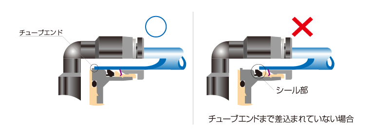
1. Make sure that the cut end face of the tube is at a right angle without a scratch or flaws on the tube surface or without elliptical deformations.
2. When installing the tube, if the tube is not inserted to the tube end (refer to Fig. above), it may cause fluid leakage.
3. After installation, pull the tube to make sure it will not come loose.
4.
(4) The following phenomena may occur when the tube is attached, but it does not necessarily mean that the tube will slip out.
(i) When observing lock-claws from the front of the release-ring, it is difficult to see lock-claws.
(Ii) There is no click feeling even if you press Release-ring.
The most common causes of tube disengagement are (1) shear drop of the tip of the lock-claws and (2) abnormal (smaller) tube diameter. Therefore, even if the above phenomena (i) and (ii) occur, install the tube according to Procedures (1) to (3).
5. The oil-free specification product has a tighter tube fit than the standard type. Be sure to insert tube up to tube end.
8-2. Precautions for Tube Insertion (Compression Fitting)
1. Make sure that the cut end face of the tube is at a right angle without a scratch or flaws on the inner and outer surface.
2. Insert the tube through the cap nut to the base of the barb. Next, use a spanner to tighten the outer hexagonal column of the cap nut that has been passed through the tube.
3.
When tightening the cap nut, refer to the tightening torque described in the connection/disconnection method of each product in the instructions.
*) Hold the tube when tightening the cap nut, since the tube may rotate along with the nut.
4. Make sure that the cap nut is against and hit the metal body. If not fit, loosen the nut, remove the tube and start over again from the process (1).
5. Make sure that there is no fluid leakage after tightening.
6. After installation, pull the tube to make sure it will not come loose.
9-1. Precautions for tube release (push-in fitting)
1. Make sure that the pressure inside the tube is zero before releasing the tube.
2. Push the release-ring of the push-in fitting evenly and deeply enough to pull out the tube toward oneself. If the release-ring is not pressed insufficiently, the tube may not come out, or the tube may be scratched and its debris may remain in the fitting.
9-2. Precautions for Tube Release (Compression Fitting)
1. Make sure that the pressure inside the tube is zero before releasing the tube.
2. Use a suitable tool on the hexagonal part of the cap nut to remove it. Then, disconnect / release the tube.
Precautions for installing product
*1) When installing the product, use an appropriate tool that does not interfere with performance, and tighten using the outer or inner hexagonal part or the outer square part. Also, when inserting a hex key into the inner hexagonal part, be careful not to let the tool come into contact with the lock-claws. Deformation at the tip of the lock-claws may reduce the holding function of the tube and cause the tube to slip out.
*2) When tightening the threaded body, refer to the tightening torque in the table blow and the allowable torque of the tool. Failure to tighten the threaded body with proper torque may result in damage to the product or tool, loosening of the thread, or leakage.
*3) Since the sealing performance of the thread is easily affected by the processing condition of the installation part, modify the installation part, use seal tape, or adjust the tightening torque according to the situation.
*4) For products whose piping direction cannot be changed by body rotation after tightening, adjust within the tightening torque range of the main body.
*5) Creep or distortion of the gasket may cause loosening in the tightening of the threaded body. Periodically check the looseness of the threaded body and retighten them with tightening torque if necessary.
Table 2 Tightening torque, Sealock (thread sealant) coating, and Gasket material
| Thread | Thread size | Tightening torque | Sealock color | Gasket material |
|---|---|---|---|---|
|
Metric thread |
M3×0.5 |
0.7N·m |
- |
SPCC+NBR |
|
Metric thread |
M3×0.5 |
0.7N·m |
- |
POM |
|
Taper pipe thread |
R1/8 |
4.5~6.5N·m |
White |
- |
|
Unified thread |
No.10-32UNF |
1~1.5N·m |
- |
SPCC+NBR |
|
NPT thread |
1/16-27NPT |
4.5~6.5N·m |
White |
- |
*) These values may differ for some products. Refer to the precautions and specification for each product as well.
11. Instructions for removal
1. When removing the product, use an appropriate tool that does not interfere with performance, and tighten using the outer or inner hexagonal part or the outer square part. Also, when inserting a hex key into the inner hexagonal part, be careful not to let the tool come into contact with the lock-claws. Deformation at the tip of the lock-claws may reduce the holding function of the tube and cause the tube to slip out.
2. Remove the sealant or a foreign substance on the removed mating thread. If the sealant adheres to the peripheral device, it may get into the devices and cause a malfunction.
12. Plumbing should be made so that fittings and tubes are not subjected to twisting, tension, moment loads, vibration, or physical impact. It may cause damaging the fitting, deforming the tube, or the tube to burst or come off.
13. Instructions for handling products
1. Impact applied by falling or else may cause damage or fluid leakage.
Common Safety Instructions for Fittings
Be sure to read the followings before selecting or using PISCO products. Read the detailed precautions, instructions and specifications for individual series.
Warning
1. Do not use water to clean products that cannot be used with water. It may cause malfunction.
Caution
1. Tighten the bulkhead nut of the bulkhead fittings within the specified tightening torque range.
Bulkhead nut tightening torque
| Series | Fitting size | Tightening torque Bulkhead Union (PM) |
Tightening torque Bulkhead Union P (PMP), Bulkhead Union Elbow (PML) |
|---|---|---|---|
|
Tube Fitting |
4 |
12.0~14.0N·m |
0.4~0.6N·m |
|
Tube Fitting |
6 |
18.0~21.0N·m |
0.9~1.1N·m |
|
Tube Fitting |
8 |
18.0~21.0N·m |
1.1~1.3N·m |
|
Tube Fitting |
10 |
19.0~21.0N·m |
2.3~2.7N·m |
|
Tube Fitting |
12 |
19.0~21.0N·m |
2.7~3.3N·m |
|
Tube Fitting |
16 |
42.0~54.0N·m |
- |
|
Tube Fitting Mini |
1.8 |
0.8~1.0N·m |
- |
|
Tube Fitting Mini |
2 |
0.8~1.0N·m |
- |
|
Tube Fitting Mini |
3 |
2.5~3.5N·m |
- |
|
Tube Fitting Mini |
4 |
5.0~7.0N·m |
- |
|
Tube Fitting Mini |
6 |
12.0~14.0N·m |
- |
2. Bulkhead nut may loose if an object between the nut is susceptible to deform or it has oil on the surface.
Common Safety Instructions for Valve Series
Be sure to read the followings before selecting or using PISCO products. Read the detailed precautions, instructions and specifications for individual series.
Warning
1. Do not operate manual valves by machine. There is a risk of damage to the product.
2. Do not use water to clean products that cannot be used with water. It may cause malfunction.
Caution
1.Refer to “Common Safety Instructions for Products Listed” and “Common Safety Instructions for Fittings” for handling fitting part.
Common Safety Instructions for Solenoid Valve Series
Be sure to read the followings before selecting or using PISCO products. Read the detailed precautions, instructions and specifications for individual series.
Warning
1.When piping, flush both the air pressure source side and the actuator side, and install an air filter (with a filtration of 5 µm or better) on the upstream side near the valve.
Drain or dust can cause malfunctions.
2.Do not use in areas exposed to water, oil or dust.
Since it is not drip-proof or explosion-proof, it may cause malfunction.
Take appropriate protective measures when using.
3.When a solenoid valve is operated under a vibration of 50m/s^2 or less, install it so that the vibration direction is perpendicular to the spool valve.
*) *Refer to the figure of “4. Installation” in “Safety Rules for Use”
4.Do not wash with water. It may cause malfunction.
Caution
1. When using the valve on the manifold, be aware that the back pressure may cause the actuator (such as a single-acting cylinder, etc.) to malfunction. In such a case, take measures such as inserting a check valve in the exhaust port.
2. Three-position valves should not be used for intermediate stops on cylinders where accuracy is required. Precise position stop is difficult due to the compressibility of air. In addition, the valve may not be able to hold the stop position for a long time because it allows leakage.
3. Do not apply strong tensile force or extreme bending to the individual plug-in connector (cable). It may cause disconnection or damage to the connector.
4. The model of 24 VDC is equipped with a surge absorber as standard to protect against surges, but surges are not completely absorbed. If there is a risk of malfunction due to surge, take additional measures.
5. When activating the valve, ensure that the leakage current is less than 1mA. Leakage current may cause malfunctions.
6. If the valve is energized in the following conditions (1) to (3), the coil will generate heat. Heat generation may shorten the product life and lead to malfunctions. It may also cause thermal burns and affect peripheral equipment. Consult with PISCO if the power is supplied under the following conditions (1) to (3).
1. (1) The power is continuously on for more than 2 hours.
2. (2) High cycle energisation.
3. (3) Even with intermittent energization, if the cumulative energized time per day is larger than non-energized time.