FAQ
Search by keyword
FAQ (Frequently Asked Questions)
The control direction of Speed Controller is different.
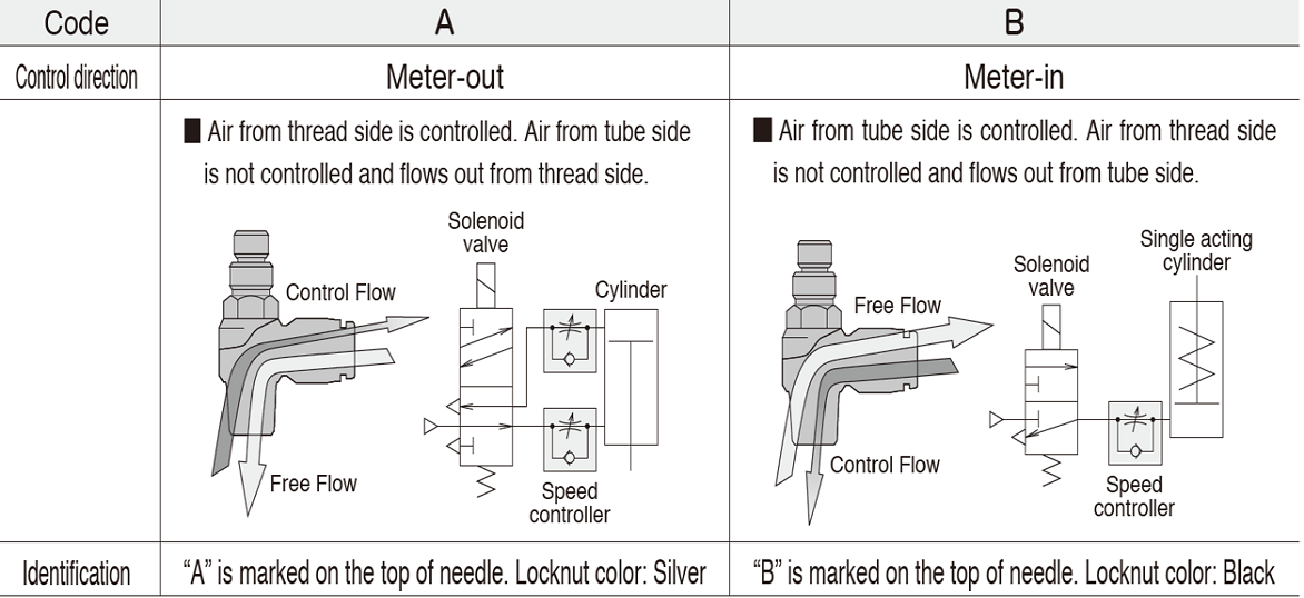

Meter-out Control
Engraving A (A□) on needle head and equipped with white color lock nut for PISCO Speed Controller.
It is mainly used for double-acting cylinders*.
It is called Meter-out control because it controls cylinder speed by regulating air flow of which exhausted from the cylinder.

Meter-in Control
Engraving B (B□) on needle head and equipped with black color lock nut for PISCO speed controller.
It is often used for single-acting cylinders*.
It is called Meter-in control because it controls cylinder speed by regulating air flow of which supply to the cylinder.
* Double-acting cylinder and Single-acting cylinder
Double-acting cylinder is designed to input pressure air to both sides of the piston, and reciprocated by force of air. Attach one piece each of Meter-out type (A) to the both cylinder ports and control extend and retract movement individually.
Single-acting cylinder is designed to input pressure air only to one side of the piston, and use force of loads or built-in spring to return. Usually attach one piece of Meter-in type (B) to the supply port of cylinder and regulate the cylinder speed of only one direction.
In general, movement of Meter-out Control is much more stable.
Meter-in Control adjusts air flow of which to supply compressed air to the cylinder.
In this circuit, pressure level of exhaust side is atmospheric pressure and it makes cylinder unstable because pressure level of inside cylinder is gradually pressurized from atmospheric pressure.
Meter-out Control fills up compressed air to both supply and exhaust side of the cylinder which stabilize movement of the cylinder.
【Movie】Meter-out/Meter-in
Double-acting cylinder is a type of the cylinder which has ports at both side of piston to allow air in. To operate double-acting cylinders, meter-out control Speed Controller is typically used.
When operate cylinder, meter-out control Speed Controller does not throttle supply air (free flow), but throttles only exhaust air at the preset flow rate. Speed controlling can be executed stably and safely in this way. On the other hand, single-acting cylinders, which return to the "home" position by the force of spring, usually use meter-in control.
【Movie】 Meter-out control and meter-in control
No. The driving force of actuators like air cylinders is depending on the degree of pressure, thus you have to decompress the supply air by regulator.
Throttling supply flow by flow control valve like Speed Controller only slow down the moving speed of cylinder but it does not concern to the driving force.
The valve that controls air flow in accordance with a purpose collectively called "flow control valve".
In PISCO, Speed Controller, Throttle Valve, Quick Exhaust Valve, Throttle (Needle) Valve and Fixed Orifice Joint are categorized into flow control valve. To control air flow for both directions, Throttle Valve is generally used. (Control air flow by opening and closing of the needle.)
Push-in fitting is the fitting to connect plastic tube for air piping and it is defined as "Push-in fitting for Thermoplastic Resin Tube" by JIS (Japanese Industrial Standard). It is connected by simply inserting tube to the fitting. When disconnect, pull the tube with pushing release-ring at the port of fitting.
This structure is widely applied for products such as Speed Controller and the products integrated with push-in fittings.
PISCO's Throttle valve and Speed controller are both categorized as control valves, besides the appearances are similar.
Differences in uses and purposes
Speed controller : Aiming to speed control of an actuator (mainly a cylinder) at the end of the plumbing.
Throttle valve: Aiming to control air flow rate at various points of plumbing.
Speed controller is mainly used to control air speed, while Throttle valve is to control air flow rate.
How to distinguish
No knurling on the outer periphery of the knob >>> Speed controller
Knurled outer periphery of the knob >>> Throttle valve
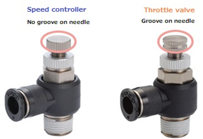
Difference in function
Speed Controller: There is a throttle valve and a check valve inside, and it is possible to control only the flow in a fixed direction (free flow when flowing in the opposite direction).
Throttle Valve: Since it does not have a Check Valve and has a structure with only a Throttle Valve, it is controlled in the same way regardless of which air is flowed.
Regulator is to be used for common device to reduce the air pressure. Pressure Controller is used to save the compressed air by reducing air pressure only during returning to "home" position when secondary pressure (pressure of output port) greatly varies caused by primary pressure (pressure of
input port) and operate actuator in high pressure.
How to use Pressure controller
2-stage Speed Controller adjusts the cylinder speed in two steps by switching the flow path of the two built-in quick exhaust valves.
The two quick exhaust valves are EX1 (determines the cylinder speed) and EX2 (determines the strength of the cushion). And this switching is the starting position of the cushion, and it is the TIM needle that determines it.
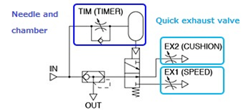
The TIM needle adjusts the flow rate when the air in the chamber (room where the air is stored) is exhausted, and the more the needle is throttled, the slower the exhaust becomes, and the switching between the two quick exhaust valves (= cushion start position) will be late.
Due to the structure, the starting position of the cushion may change due to external factors (applied pressure, pipe diameter and length, increase / decrease in cylinder sliding resistance, etc.).
▼1)
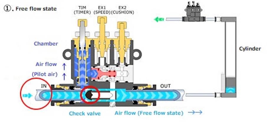
The air applied from the IN side flows in two directions, the chamber part (TIM) side and the OUT side.
▼2)
The air that has flowed to the OUT side (free flow state) flows to the cylinder.
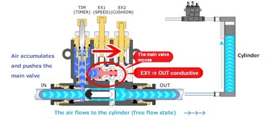
At the same time, air also accumulates in the chamber (TIM), pushing the main valve to the right (the function of pilot air), and the EX1 and OUT sides become conductive.
▼3)
When the exhaust 1 state (when adjusting the cylinder speed) is reached, air is exhausted to the flow path (OUT side → EX1) that was conducted in 2).
(Due to the check valve, it does not flow to the IN side)
At the same time, the air accumulated in the chamber is adjusted by the TIM needle and exhausted from the IN side.
At this time, you can adjust the timing of switching to the cushion by adjusting the TIM needle.
▼4)
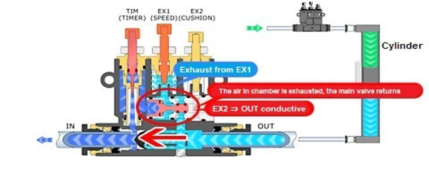
The air adjusted by the EX1 needle is exhausted from the EX1.
(Same as the function of the Quick Exhaust Valve)
At this time, when the air in the chamber is exhausted, the main valve returns to the left side and the EX2 and OUT sides are connected.
▼5)
The air in the chamber disappeared, the main valve moved to the left, and the EX2 and OUT sides became conductive.
The air flowing to EX2 is exhaust-adjusted by EX2 needle and exhausted from EX2.
This state is the exhaust 2 state (cushion adjustment).
At this time, the strength of the cushion can be adjusted by adjusting the EX2 needle.
It can be distinguished from the marking on the main body.
The front is the marked side and the rear is the side without marking.
The direction of the air flow is through from right to left in the below picture and illustration.
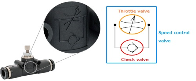
The above engraved circuit diagram indicates "Speed Controller".
To be more specific, the symbol encircled in orange is Throttle Valve (valve that throttles, adjusts air flow) and encircled in red is check valve (valve that allows air to flow in by only one direction).
Control direction is determined by the direction of check valve*.
*) Direction of free flow is from right to the left when symbol is ">", to the direction to be wider.
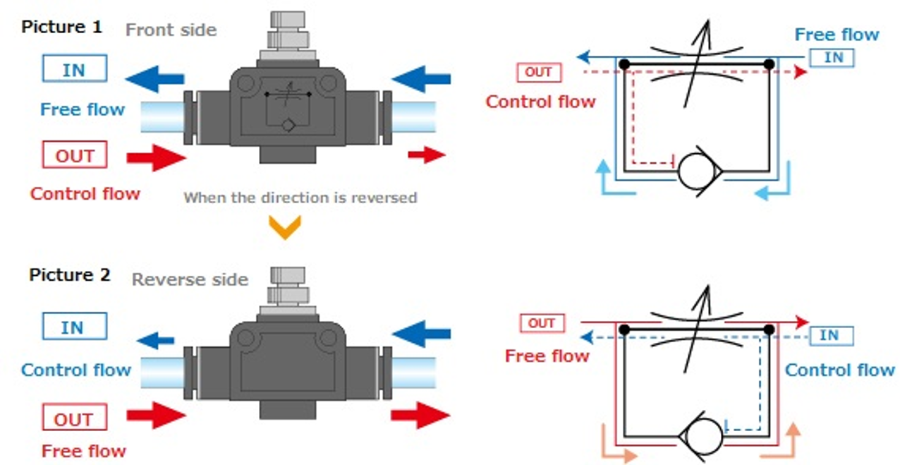
When free flow of entering air (supplying air to a cylinder) is required,
which is Meter-out control, set the direction of air and the check valve as same as Illustration 1. (Return air, which is exhausted air from the cylinder, is controlled.)
On the other hand, when free flow of coming out air from a cylinder is required,
which is meter-in control ,set the direction of air and the Check Valve as same as Illustration 2.(Entering air which is supplied to the cylinder is controlled.)
Exchange the front and back side from the position illustrated in 1, and meter-in control can be made.
The construction of Speed Controller Union Straight type is as mentioned above. Meter-in and meter-out control should be chosen according to the direction of plumbing.When installing a Speed Controller in a plumbing, make sure the direction of air flow
Because Push-in fitting seals outside diameter of tube by an elastic-sleeve (rubber seal), there may be a factor causing leak, such as scratches, deformation or jamming of contaminants.
The fittings are designed for pressurized air piping, then they cannot be used for the circuit of gas or liquid which becomes a risk upon leakage, or for an inspection equipment which becomes easily affected by even slight leak.
Search by category
If your problem is not solved, please contact us from the following link.
You will be contacted by a representative at a later date.
If you are in a hurry or would like to contact our sales office directly by phone, please see the list of sales offices.
