Pressure Sensor & Switch
2-Color Digital Flow Sensor 21
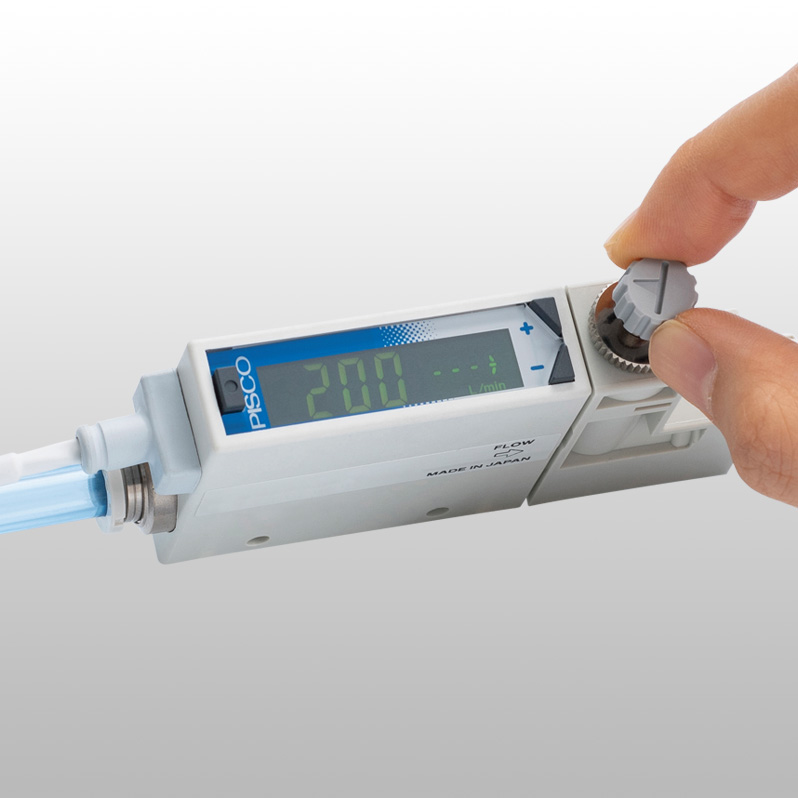
Flow management and suction lift verification of small work piece are possible.
Advantages
Flow management and suction verification of small work piece are possible.
High accuracy: Max. ± 3% F.S.
Precise flow measurement is possible.
Quick response time: Max. 50 msec.
High-speed response is realized by incorporating a platinum sensor chip processed with silicon micromachining and contributes to shorten cycle time.
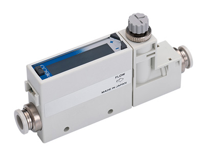
Built-in needle valve model.
Flow adjustable needle valve and sensor are integrated into one unit. Easy piping and space saving.
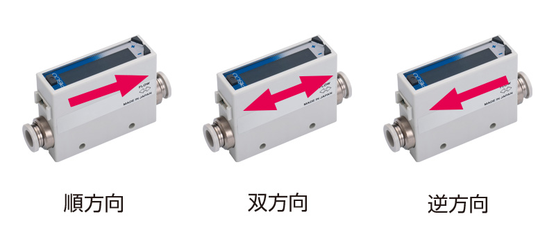
Bi-directional flow measurement is possible.
Bi-directional flow model allows for pre-setting the flow direction as desired, which gives you installation flexibility. It can be used as a reverse flow detector.
Convenient display function is provided.
Reversible display function allows the orientation of display to rotate when the sensor is used upside down.

2-color/dual display contributes to enhancing operability.
Operability is enhanced by the dual display. 2-color display allows for detecting abnormalities at a glance.

Flexible mounting options
By a mounting bracket, a panel mount bracket or a DIN rail mount bracket

No straight piping section required.
No straight piping section is required at either upstream or downstream side.
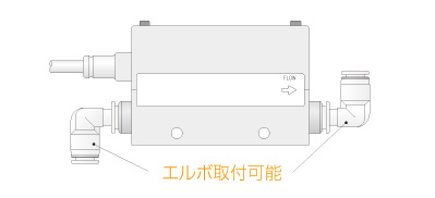
A variety of connections
Inch sizes are newly added.
Setting copy function is equipped.
Settings on master sensor can be copied to slave sensors.
Five types of gases can be measured.
Gas type switching functions is equipped.
Specifications
Common spec.
| Fluid medium(*1) | Clean air (JIS B 8392-1:2012 1.1.1 to 5.6.2), Compressed air(JIS B 8392-1:2012 1.1.1 to 1.6.2), nitrogen gas, argon gas, carbon dioxide gas, mixed gas(argon+carbon dioxide) |
|---|---|
| Temp. range | 0 to 50ºC (no freezing) |
| Pressure range | -0.09MPa to 0.75MPa |
| Pressure proof | 1MPa |
| Operating ambient temp. and hum. | 0 to 50ºC, 90%RH or less |
| Storage temperature | -10 to 60℃ |
| Accuracy(*2)(*3) | ±3%F.S. or less(Secondary side released to atmosphere)(The scope of warranty is in accordance with the "measurement flow rate range") |
| Repeatability(*4) | ±1%F.S. or less(Secondary side released to atmosphere) |
| Temperature characteristics | Within ±0.2%F.S./ºC(15 to 35ºC, 25ºC criteria) |
| Pressure characteristics | Within ±5%F.S.(Criteria: secondary side released to atmosphere) / For flor rate 201 model:Within ±5%F.S.(Criteria: 0.35) |
| Response time(*5) | 50msec or less(When response time setting is OFF) |
| Switch output (NV/NVC/NA/NAC) | NPN open collector output(50mA or less, voltage drop 2.4V or less) |
| Switch output (PV/PVC/PA/PAC) | PNP open collector output(50mA or less, voltage drop 2.4V or less) |
| Analog output(*6) (NV/NVC/PV/PVC) | 1to 5V voltage output(connecting load impedance 50kΩor less) |
| Analog output(*6) (NA/NAC/PA/PAC) | 4 to 20mA current output(connecting load impedance 0 to 300Ωor less) |
| Power supply voltage(*7) (NV/NVC/PV/PVC) | DC12 to 24V (10.8 to 26.4V) ripple rate 1% or less |
| Power supply voltage(*7) (NA/NAC/PA/PAC) | DC24V (21.6 to 26.4V) ripple rate 1% or less |
| Current consumption(*8) | 45mA or less |
| Lead wire | ø3.7, AWG26 or equivalent x 5-conductor (connector), insulator O.D. ø1.0 |
| Functions(*9) | (1) Gas type switching, (2) Setting copy function, (3) Flow rate integration, (4) Peak hold, et.c |
| IP rating | IP40 equivalent |
| Protection circuit(*10) | Power supply severse connection protection, switch output reverse connection protection and switch output load short-circuit protection |
| Vibration resistance | 10 to 150Hz, max.100m/s², 2 hours each in X, Y, Z direction |
| EMC Directive | EN55011, EN61000-6-2, EN61000-4-2/3/4/6/8 |
| Mounting orientaion(*11) | Unrestricted in vertical/horozontal direction |
| Straight piping section(*12) | Not required |
*1. Use dry gas which does not contain corrosive elements such as chlorine, sulfur or acids, and which is clean and does not contain dust or oil mist. When using compressed air, use clean air that complies with JIS B 8392-1:2012 Class 1.1.1 to 1.6.2. Compressed air from the compressor contains drain (water, oil oxide, foreign substances, etc.). To maintain the function of the product, install a filter, air dryer (min. pressure dew point 10°C or less), and oil mist filter (max. oil content concentration 0.1 mg/m³) on the upstream side of the product.

*2. Compressed air is used for adjustment and inspection of this product. Accuracy for gas types other than air is only a guide.
*3. The accuracy is based on the manufacturer's standard flow rate meter. It does not represent absolute accuracy. Repeatability, temperature characteristics, and pressure characteristics are not included in accuracy ± 3% F.S. Take a nessessary step depending on the operating environment and conditions.
*4. Repeatability is calculated during a short period of time. Aging variation is not included.
*5. Actual response time may differ depending on piping conditions. Response time can be set within the range of 50 msec. to 1.5 sec.
*6. The output impedance of analog output type is about 1kΩ. In the case the impedance of the connecting load is low, output and error increase. Check error with the connecting load before using.
*7. The power supply voltage specifications differ for the voltage output type and the current output type.
*8. Current when 24 VDC is connected and no load is applied. The current consumption will vary depending on how the load is connected.
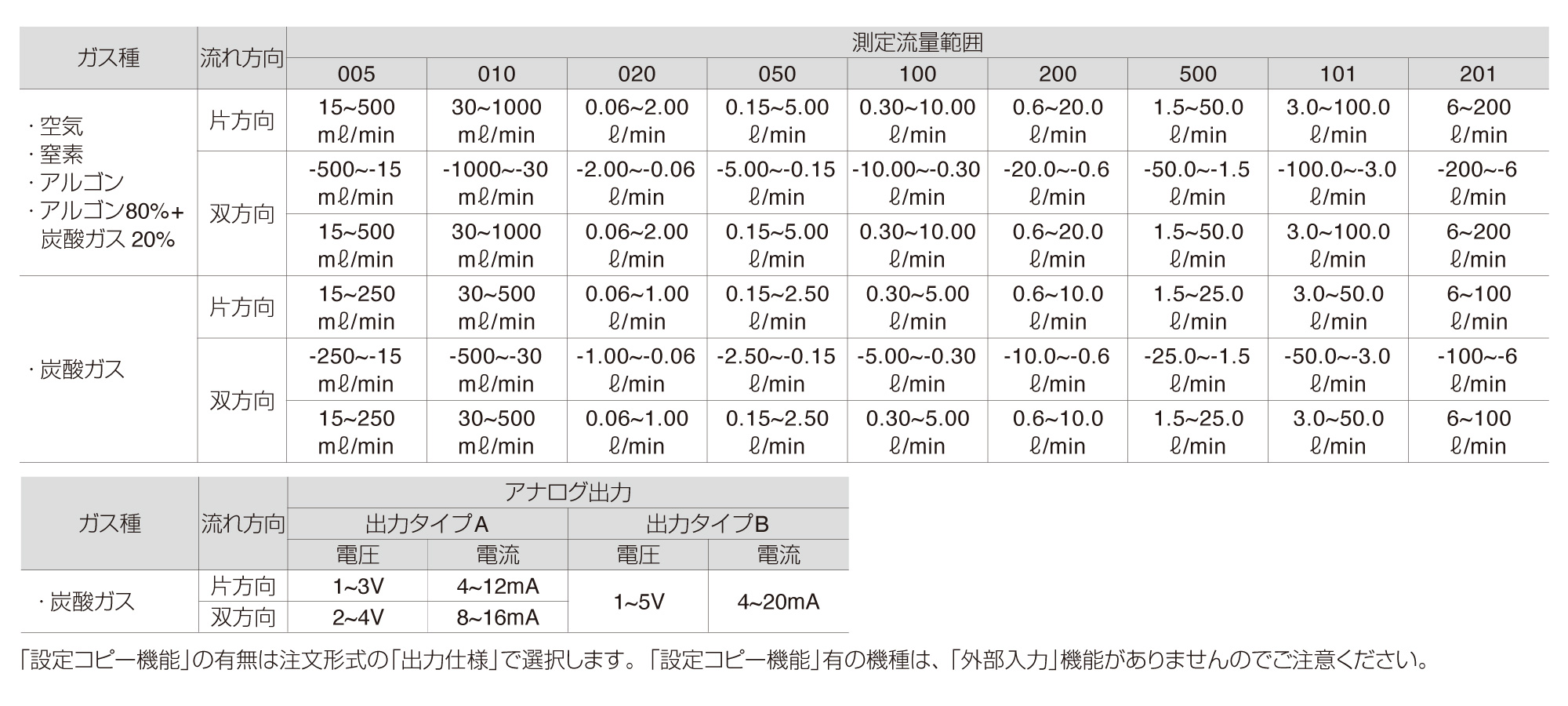
*9. The gas type switching function enables it to switch to argon, carbon dioxide, argon 80% + carbon dioxide 20%. The details are as follows. Note that the full scale flow rates become half of those of the flow rate range when switching to carbon dioxide gas.
*10. The protection circuit of this product is effective only for specific error connections and load short-circuits. It does not provide protection for all misconnections.
*11. The product measures changes in heat distribution caused by flow. If installed vertically, the heat distribution may change due to theeffect of convection, and the zero point can shift.
*12. Accuracy may be affected by the piping conditions. For more accurate measurement, provide a straight pipe section 10 times as long as the pipe inner diameter.
Flow rate range 0.5L/min type spec.
| Full scale flow rate | 0.5L/min |
|---|---|
| Flow direction | F: Uni-direction / R: Bi-direction |
| Flow rate measurement range(*1)(F) | 15 to 500mL/min |
| Flow rate measurement range(*1)(R) | -500 to -15, 15 to 500mL/min |
| Dispaly type | 4 digits+4 digits 2-color LCD |
| Flow rate display range(*2)(F) | -49 to 549mL/min |
| Flow rate display range(*2)(R) | -549 to 549mL/min |
| Integrated display(*3) range | 0 to ±9999999mL |
| Integrated display(*3) pulse output rate | 5mL |
*1. The value converted from mass flow rate to volumetric flow rate at standard condition (20°C, 1 barometric pressure (101 kPa), relative humidity 65%). (For gas other than air, 20°C, 1 barometric pressure (101 kPa), relative humidity 0%RH).
*2. The displays of each flow rate are shown below.

*3. The integrated flow is a calculated (reference) value. When using the integrated value save function, the number of saves should not exceed the access count limit of the storage cell (1 million times). (Changes to the settings are counted in number of accesses.)

Flow rate range 1L/min type spec.
| Full scale flow rate | 1L/min |
|---|---|
| Flow direction | F: Uni-direction / R: Bi-direction |
| Flow rate measurement range(*1)(F) | 30 to 100mL/min |
| Flow rate measurement range(*1)(R) | -1000 to -30, 30 to 1000mL/min |
| Display type | 4 digits+4 digits 2-color LCD |
| Flow rate display range(*2)(F) | -99 to 1099mL/min |
| Flow rate display range(*2)(R) | -1099 to 1099mL/min |
| Integrated display(*3) range | 0 to ±9999999mL |
| Integrated display(*3) pulse output rate | 10mL |
*1. The value converted from mass flow rate to volumetric flow rate at standard condition (20°C, 1 barometric pressure (101 kPa), relative humidity 65%). (For gas other than air, 20°C, 1 barometric pressure (101 kPa), relative humidity 0%RH).
*2. The displays of each flow rate are shown below.

*3. The integrated flow is a calculated (reference) value. When using the integrated value save function, the number of saves should not exceed the access count limit of the storage cell (1 million times). (Changes to the settings are counted in number of accesses.)

Flow rate range 2L/min type spec.
| Full scale flow rate | 2L/min |
|---|---|
| Flow direction | F:Uni-direction / R:Bi-direction |
| Flow rate measurement range(*1)(F) | 0.06 to 2.00L/min |
| Flow rate measurement range(*1)(R) | -2.00 to -0.06, 0.06 to 2.00L/min |
| Display type | 4 digits+4 digits 2-color LCD |
| Flow rate display range(*2)(F) | -0.19 to 2.19L/min |
| Flow rate display range(*2)(R) | -2.19 to 2.19L/min |
| Integrated display(*3) range | 0.00 to ±99999.99L |
| Integrated display(*3) pulse output rate | 0.02L |
*1. The value converted from mass flow rate to volumetric flow rate at standard condition (20°C, 1 barometric pressure (101 kPa), relative humidity 65%). (For gas other than air, 20°C, 1 barometric pressure (101 kPa), relative humidity 0%RH).
*2. The displays of each flow rate are shown below.

*3. The integrated flow is a calculated (reference) value. When using the integrated value save function, the number of saves should not exceed the access count limit of the storage cell (1 million times). (Changes to the settings are counted in number of accesses.)

Flow rate range 5L/min type spec.
| Full scale flow rate | 5L/min |
|---|---|
| Flow direction | F: Uni-direction / R: Bi-direction |
| Flow rate measurement range(*1)(F) | 0.15 to 5.00L/min |
| Flow rate measurement range(*1)(R) | -5.00 to -0.15, 0.15 to 5.00L/min |
| Display type | 4 digits+4 digits 2-color LCD |
| Flow rate display range(*2)(F) | -0.49 to 5.49L/min |
| Flow rate display range(*2)(R) | -5.49 to 5.49L/min |
| Integrated display(*3) range | 0.00 to ±99999.99L |
| Integrated display(*3) pulse output rate | 0.05L |
*1. The value converted from mass flow rate to volumetric flow rate at standard condition (20°C, 1 barometric pressure (101 kPa), relative humidity 65%). (For gas other than air, 20°C, 1 barometric pressure (101 kPa), relative humidity 0%RH).
*2. The displays of each flow rate are shown below.

*3. The integrated flow is a calculated (reference) value. When using the integrated value save function, the number of saves should not exceed the access count limit of the storage cell (1 million times). (Changes to the settings are counted in number of accesses.)

Flow rate range 10L/min type spec.
| Full scale flow rate | 10L/min |
|---|---|
| Flow direction | F: Uni-direction / R: Bi-direction |
| Flow rate measurement range(*1)(F) | 0.30 to 10.00L/min |
| Flow rate measurement range(*1)(R) | -10.00 to -0.30, 0.30 to 10.00L/min |
| Display type | 4 digits+4 digits 2-color LCD |
| Flow rate display range(*2)(F) | -0.99 to 10.99L/min |
| Flow rate display range(*2)(R) | -10.99 to 10.99L/min |
| Integrated display(*3) range | 0.00 to ±99999.99L |
| Integrated display(*3) pulse output rate | 0.1L |
*1. The value converted from mass flow rate to volumetric flow rate at standard condition (20°C, 1 barometric pressure (101 kPa), relative humidity 65%). (For gas other than air, 20°C, 1 barometric pressure (101 kPa), relative humidity 0%RH).
*2. The displays of each flow rate are shown below.

*3. The integrated flow is a calculated (reference) value. When using the integrated value save function, the number of saves should not exceed the access count limit of the storage cell (1 million times). (Changes to the settings are counted in number of accesses.)

Flow rate rage 20L/min type spec.
| Full scale flow rate | 20L/min |
|---|---|
| Flow direction | F: Uni-direction / R: Bi-direction |
| Flow rate measurement range(*1)(F) | 0.6 to 20.0L/min |
| Flow rate measurement range(*1)(R) | -20.0 to -0.6, 0.6 to 20.0L/min |
| Display type | 4 digits+4 digits 2-color LCD |
| Flow rate display range(*2)(F) | -1.9 to 21.9L/min |
| Flow rate display range(*2)(R) | -21.9 to 21.9L/min |
| Integrated display(*3) range | 0.0 to ±999999.9L |
| Integrated display(*3) pulse output rate | 0.2L |
*1. The value converted from mass flow rate to volumetric flow rate at standard condition (20°C, 1 barometric pressure (101 kPa), relative humidity 65%). (For gas other than air, 20°C, 1 barometric pressure (101 kPa), relative humidity 0%RH).
*2. The displays of each flow rate are shown below.

*3. The integrated flow is a calculated (reference) value. When using the integrated value save function, the number of saves should not exceed the access count limit of the storage cell (1 million times). (Changes to the settings are counted in number of accesses.)

Flow rate range 50L/min type spec.
| Full scale flow rate | 50L/min |
|---|---|
| Flow direction | F: Uni-direction / R: Bi-direction |
| Flow rate measurement range(*1)(F) | 1.5 to 50.0L/min |
| Flow rate measurement range(*1)(R) | -50.0 to -1.5, 1.5 to 50.0L/min |
| Display type | 4 digits+4 digits 2-color LCD |
| Flow rate display range(*2)(F) | -4.9 to 54.9L/min |
| Flow rate display range(*2)(R) | -54.9 to 54.9L/min |
| Integrated display(*3) range | 0.0~±999999.9L |
| Integrated display(*3) pulse output rate | 0.5L |
*1. The value converted from mass flow rate to volumetric flow rate at standard condition (20°C, 1 barometric pressure (101 kPa), relative humidity 65%). (For gas other than air, 20°C, 1 barometric pressure (101 kPa), relative humidity 0%RH).
*2. The displays of each flow rate are shown below.

*3. The integrated flow is a calculated (reference) value. When using the integrated value save function, the number of saves should not exceed the access count limit of the storage cell (1 million times). (Changes to the settings are counted in number of accesses.)

Flow rate range 100L/min type spec.
| Full scale flow rate | 100L/min |
|---|---|
| Flow direction | F: Uni-direction / R: Bi-direction |
| Flow rate measurement range(*1)(F) | 3.0 to 100.0L/min |
| Flow rate measurement range(*1)(R) | -100.0 to -3.0, 3.0 to 100.0L/min |
| Display type | 4 digits+4 digits 2-color LCD |
| Flow rate display range(*2)(F) | -9.9 to 109.9L/min |
| Flow rate display range(*2)(R) | -109.9 to 109.9L/min |
| Integrated display(*3) range | 0 to ±999999.9L |
| Integrated display(*3) pulse output rate | 1L |
*1. The value converted from mass flow rate to volumetric flow rate at standard condition (20°C, 1 barometric pressure (101 kPa), relative humidity 65%). (For gas other than air, 20°C, 1 barometric pressure (101 kPa), relative humidity 0%RH).
*2. The displays of each flow rate are shown below.

*3. The integrated flow is a calculated (reference) value. When using the integrated value save function, the number of saves should not exceed the access count limit of the storage cell (1 million times). (Changes to the settings are counted in number of accesses.)

Flow rate range 200L/min type spec.
| Full scale flow rate | 200L/min |
|---|---|
| Flow direction | F: Uni-direction / R: Bi-direction |
| Flow rate measurement range(*1)(F) | 6 to 200L/min |
| Flow rate measurement range(*1)(R) | -200 to -6, 6 to 200L/min |
| Display type | 4 digits+4 digits 2-color LCD |
| Flow rate display range(*2)(F) | -19 to 219L/min |
| Flow rate display range(*2)(R) | -219 to 216L/min |
| Integrated display(*3) range | 0 to ±9999999L |
| Integrated display(*3) pulse output rate | 2L |
*1. The value converted from mass flow rate to volumetric flow rate at standard condition (20°C, 1 barometric pressure (101 kPa), relative humidity 65%). (For gas other than air, 20°C, 1 barometric pressure (101 kPa), relative humidity 0%RH).
*2. The displays of each flow rate are shown below.

*3. The integrated flow is a calculated (reference) value. When using the integrated value save function, the number of saves should not exceed the access count limit of the storage cell (1 million times). (Changes to the settings are counted in number of accesses.)

Port size
Tube dia.
| mm size (mm) | φ4, φ6, φ8, φ10 |
|---|---|
| inch size | φ1/4", φ3/8" |
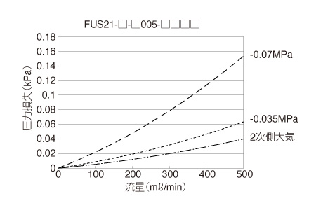
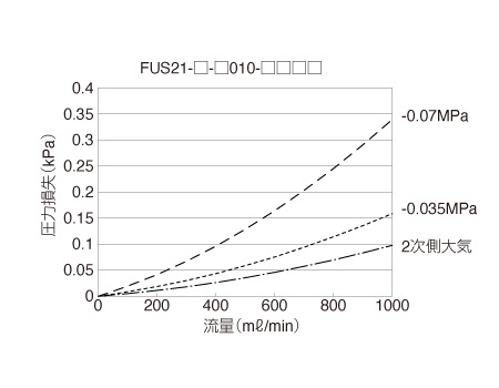
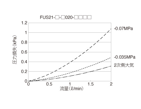
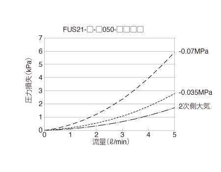
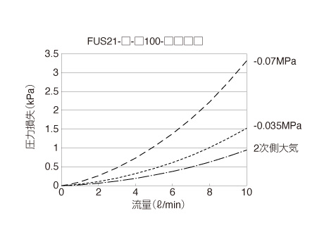
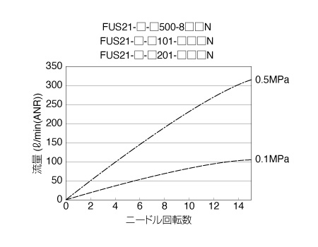
Characteristic Graph
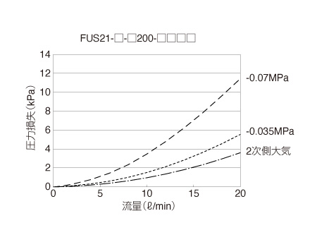
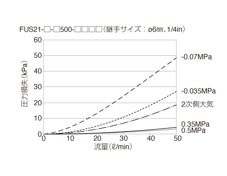
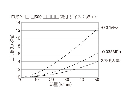
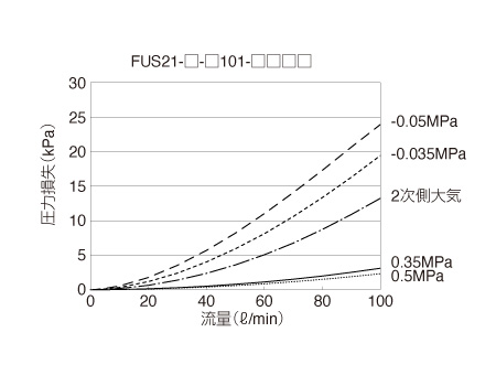
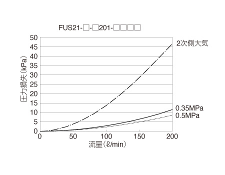
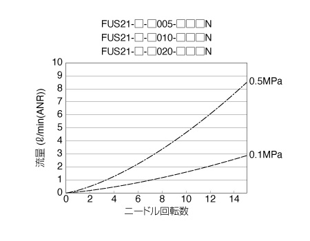
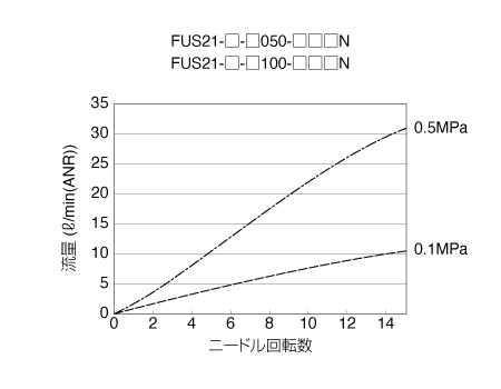
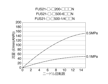
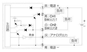
Circuit Diagram
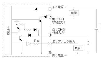
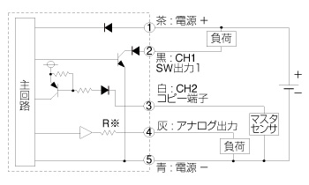
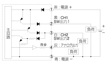
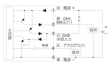
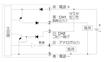
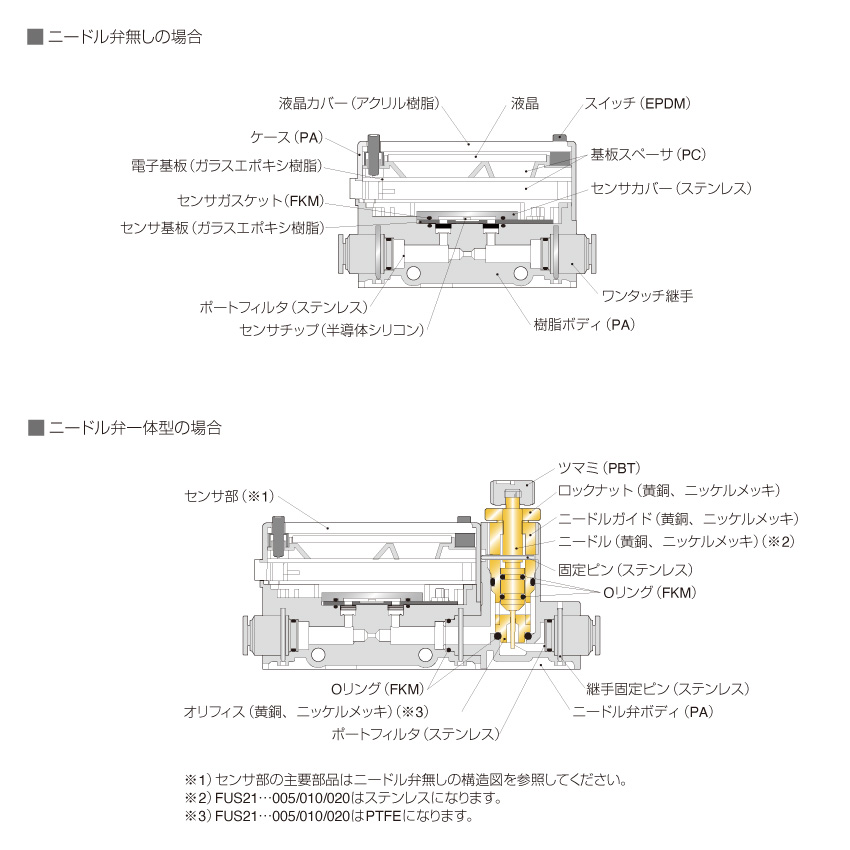
Construction
Type & Price list
Detailed Safety Instructions
Warning
1.This product cannot be used as a business meter.
2.Use dry gas which does not contain corrosive elements such as chlorine, sulfur or acids, and clean gas which does not contain dust or oil mist. Depending on the fluid, retaining the fluid for long periods could adversely affect the performance. Do not seal the fluid in the system for long periods of time. Also, if foreign objects such as dusts, water droplets, oil-mist is drawn in the system, it can affect the accuracy of the measurements and cause malfunction. To avoid such contaminations, install a filter, air dryer and an oil mist filter on the primary side (upstream side) of the product.
3.When using a valve on the primary side of this product, use only an oil-prohibited specification valve. This sensor could malfunction or fail if exposed to splattering grease, oil, etc. As friction powder may be generated depending on the valve, mount a filter to prevent the powder from entering the sensor.
4.When using liquefied gas such as carbon dioxide, always vaporize it first. Failure may result if liquefied gas enters the product.
Caution
1.Although the sensor can handle an overflow double the measurement range, do not use it under condition beyond the specified range.
2.Applications exceeding the max. working pressure and specified flow rate range may result in faults. If energized in a vacuum state of −0.09 MPa or less, the sensor's heat dissipation will suffer, leading to degradation of the sensor. Even within the pressure range, the excessive flow may occur due to pressure difference between upstream and downstream sides and the sensor may operate abnormally. In case of using with high pressure, provide a bypass circuit or restrictor so that excessive flow is not applied to the sensor.
3.The needle valve permits minute leakage. Do not use the products for the application that requires no leakage.
4.The flow path is not completely free of dust generation. Use Hollow Fiber Membrane Filter together if dust generation could be a problem.
5.Be aware of the following points in case of use for suction verification, etc. 1. Mount an air filter upstream from suction in compliance with the working status to prevent the entry of foreign matter. 2. Consider the atmospheric dew point and the product's ambient temperature, and use the product under conditions in which dew does not condense in pipes. 3. Xxx 4. When the suction confirmation sensor is switched from a pressure sensor (switch) to a flow rate sensor (switch), sensor output (switch output) logic will be reversed. Refer to the drawing below. Note that the PLC sequence program must be changed or revised. If source pressure or vacuum source is not supplied when device power is turned ON, "flow rate 0" = "sensor output (switch output) ON" status is set at the flow rate sensor (switch). Check that this is not a problem with the PLC sequence program, etc. 5. Select the flow rate range based on the operating vacuum pressure and suction nozzle. Response speed may be delayed by the piping volume between the suction nozzle and this product. In this case, take countermeasures to reduce piping capacity.

6.The case is made of resin. Do not use solvent, alcohol or detergent in cleaning, since the resin could absorb it. There is a risk of affecting the resin. Wipe off dirt with a rag soaked in a diluted neutral detergent solution and wrung out well.
7.The accuracy may vary from the initial status depending on the working environment or operating conditions. It is recommended to check the operation of the product periodically. Also, the sensor chip will degrade when used for long periods of time and cause the detected flow rate to fluctuate. Inspect the sensor chip periodically.
Frequently Asked Questions for Pressure Sensor & Switch Series
If the pressure is not displayed on the separate display, check the following.
1)
Incorrect connection (wiring) of the connector cable
2)
Is the sensor head "analog output type"?
(Please note that the pressure indicator cannot be used with the "switch output type" sensor head.)
3)
Does the sensor type setting match the rated pressure range of the sensor head (sensor input specifications)?
Does the sensor type settings ("C-1 (compound pressure)", "C-2 (positive pressure)", "C-3 (negative pressure)") match the rated pressure range (sensor input specifications) of your sensor head ? Please check if they match. If you set a different sensor type, the correct value will not be displayed.
SED-31 sensor type setting and recommended sensor head (Reference: Excerpt from our catalog)
「C-1(compound pressure)」 VUS11-□AR
「C-2(positive pressure )」 VUS11-□A、VUS12-□A
「C-3(negative pressure)」 SEU11-□A
*)
Damaged sensor head
If a voltage higher than the power supply (V) of the sensor head and display is applied, the sensor head and display may be damaged, and as a result, the pressure may not be displayed on the pressure display. Be sure to use it within the range of the power supply (V) of the sensor head.
Inquiries about this product
It is also possible to suggest products suitable for various conditions such as applications and functions. Please feel free to contact us or visit the nearest sales office.
The following are frequently asked questions. Please check before making inquiries.
