Control Valve
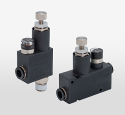
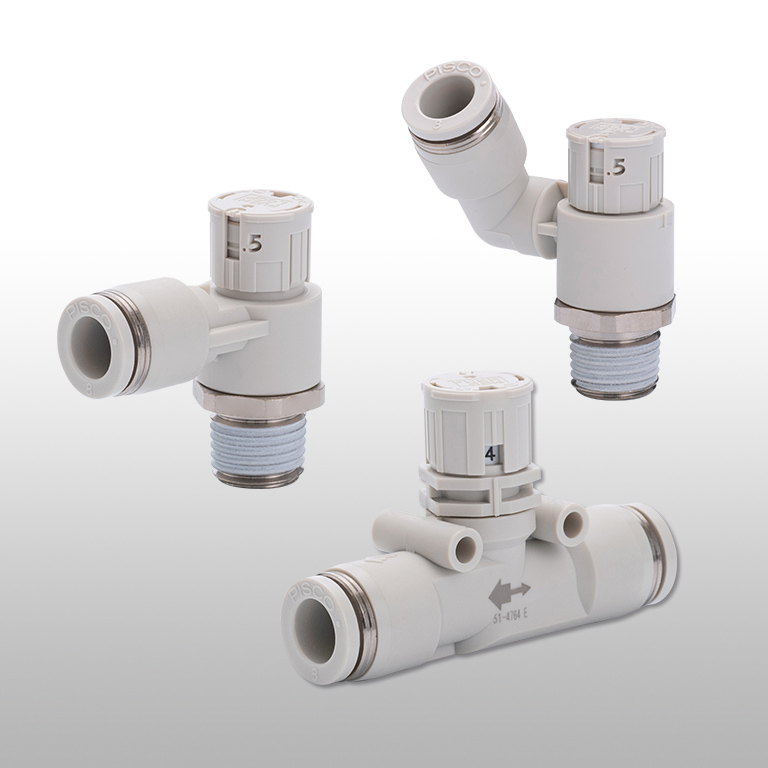
Speed controller Push-lock type with Indicator
Speed setting can be checked with indicator.
Easy adjustment due to its liner characteristics.
Options
-
Fluorine grease is used as grease, and the product is packaged in a clean room after cleaning with clean air.
Advantages
Speed setting can be checked with indicator.
Easy adjustment due to its liner characteristics.
Flow rate can be set with indicator. The scales are on the side(upper/lower) and the top.

Flow rate is proportional to the knob turns.
2 types with different flow range for each size are available. Easier fine adjustment is possible in each flow range, compared to Pisco conventional standard speed controller.

It has a very compact body. The industry's smallest and low profile as a speed controller with an indicator.

Push-Lock type knob. Easy to handle.
Flow rate can be set by 30 steps in one turn. * The number of turn is visible every 1/2 turn.

Easy to identify the flow direction by the knob color.

The indicator window of Union straight type can be rotated 360°.

The material of the diaphragm is HNBR.
Free type can be set in any direction for tubing.
The fitting part rotates in addition to the resin body.

Clean-room packaging specifications are available for speed control in a clean environment. (Optional)
Fluorine-based grease is used and packaged in a clean-room (equivalent to ISO class 6) after being cleaned with clean air.
Low cracking pressure type is available.
Ideal for use on single-acting low cracking pressure type cylinders.
Specifications
| Fluid medium | Air |
|---|---|
| Operating pressure range | 0.1~1.0MPa |
| Check valve opening pressure | 0.05MPa |
| Operating temp. range | 0~60℃ (No freezing) |
Port size
Tube dia.
| mm size(mm) | φ3, φ4, φ6, φ8, φ10, φ12 |
|---|---|
| inch size | φ1/8, φ5/32, φ3/16, φ1/4, φ5/16, φ3/8, φ1/2 |
Thread size
| Metric male thread | M3x0.5, M5x0.8 |
|---|---|
| Taper pipe male thread | R1/8, R1/4, R3/8, R1/2 |
| UNF Thread | 10-32UNF |
| NPT Thread | NPT1/8, NPT1/4, NPT3/8, NPT1/2 |
Flow Characteristic Graph


Type & Price list
Detailed Safety Instructions
Warning
1.When adjusting the speed of the actuator, the needle, inside the product, should be gradually opened from the closed position near the dial indication "0". When the needle is open, a large flow of compressed air is instantly supplied and there is a danger of the actuator moving suddenly and violently. The operation depending on the direction of rotation of the adjustment knob is as follows. Clockwise (- direction): the needle valve closes, the control flow is reduced and the actuator speed is reduced. Counter-clockwise (+ direction): the needle valve opens and the control flow increases and the actuator speed increases.
2.When adjusting the position of elbow fittings, do not apply pressure to the inside of the product.
3.When adjusting the direction of the dial display window on union-type models, do not apply pressure to the inside of the product.
Caution
1.Leakage is allowed for the control flow even when the needle is fully closed in the state of dial indication "0" position and should not be used in such a way that zero leakage is required. Also, depending on how hard the needle is tightened, it may shift from the position where the dial display is "0".
2.Flow rate characteristics are reference values for the product alone and vary depending on piping, circuit, pressure conditions, etc.
3.The adjustment knob is locked when pushed and released when pulled. Be sure to lock it after adjustment. Do not hold the side of the knob too tightly when operating, as it may not be able to unlock it.
4.Be sure to lock it after adjusting the flow rate. If used without locking, the adjustment knob may rotate and the flow rate may change.
5.When pushing in the adjustment knob, depending on the adjusting position, it may stop in a half-locked position between the locked and unlocked states. Make sure that the adjustment knob is pushed completely in to the locked position, as the knob is not fully locked in this state.
6.If the adjustment knob is forcibly rotated while it is in locked position, the lock mechanism may be damaged.
7.Do not turn the adjustment knob excessively counter-clockwise (+ direction) from the fully open position or clockwise (- direction) from the fully closed position. It may cause damage to the adjustment knob and the product.
8.The control range varies depending on the size. When adjusting the flow rate, check the current dial reading and adjust it within the indicator adjusting range shown in the following Table.

9.The direction of the dial indication window on the union type should only be adjusted after ensuring that the spanner is securely applied to the hexagonal-column. There is a risk of deformation or interference with the adjustment knob.
Frequently Asked Questions for Control Valve Series
The control direction of Speed Controller is different.
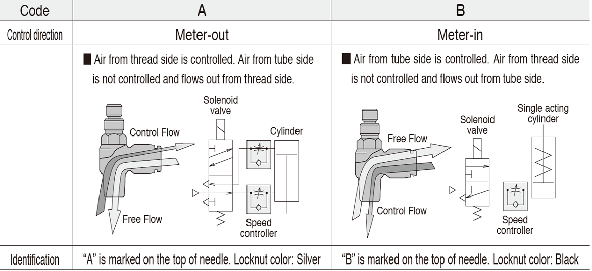

Meter-out Control
Engraving A (A□) on needle head and equipped with white color lock nut for PISCO Speed Controller.
It is mainly used for double-acting cylinders*.
It is called Meter-out control because it controls cylinder speed by regulating air flow of which exhausted from the cylinder.

Meter-in Control
Engraving B (B□) on needle head and equipped with black color lock nut for PISCO speed controller.
It is often used for single-acting cylinders*.
It is called Meter-in control because it controls cylinder speed by regulating air flow of which supply to the cylinder.
* Double-acting cylinder and Single-acting cylinder
Double-acting cylinder is designed to input pressure air to both sides of the piston, and reciprocated by force of air. Attach one piece each of Meter-out type (A) to the both cylinder ports and control extend and retract movement individually.
Single-acting cylinder is designed to input pressure air only to one side of the piston, and use force of loads or built-in spring to return. Usually attach one piece of Meter-in type (B) to the supply port of cylinder and regulate the cylinder speed of only one direction.
In general, movement of Meter-out Control is much more stable.
Meter-in Control adjusts air flow of which to supply compressed air to the cylinder.
In this circuit, pressure level of exhaust side is atmospheric pressure and it makes cylinder unstable because pressure level of inside cylinder is gradually pressurized from atmospheric pressure.
Meter-out Control fills up compressed air to both supply and exhaust side of the cylinder which stabilize movement of the cylinder.
【Movie】Meter-out/Meter-in
"A" is the meter-out control and "B" is the meter-in control.
For the difference between meter-out and meter-in, see FAQ "What is the difference between meter-out control and meter-in control of speed controller?".
Double-acting cylinder is a type of the cylinder which has ports at both side of piston to allow air in. To operate double-acting cylinders, meter-out control Speed Controller is typically used.
When operate cylinder, meter-out control Speed Controller does not throttle supply air (free flow), but throttles only exhaust air at the preset flow rate. Speed controlling can be executed stably and safely in this way. On the other hand, single-acting cylinders, which return to the "home" position by the force of spring, usually use meter-in control.
【Movie】 Meter-out control and meter-in control
No. The driving force of actuators like air cylinders is depending on the degree of pressure, thus you have to decompress the supply air by regulator.
Throttling supply flow by flow control valve like Speed Controller only slow down the moving speed of cylinder but it does not concern to the driving force.
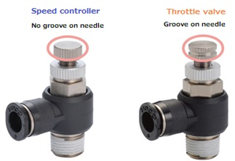
PISCO's Throttle valve and Speed controller are both categorized as control valves, besides the appearances are similar.
Differences in uses and purposes
Speed controller : Aiming to speed control of an actuator (mainly a cylinder) at the end of the plumbing.
Throttle valve: Aiming to control air flow rate at various points of plumbing.
Speed controller is mainly used to control air speed, while Throttle valve is to control air flow rate.
How to distinguish
No knurling on the outer periphery of the knob >>> Speed controller
Knurled outer periphery of the knob >>> Throttle valve
Difference in function
Speed Controller: There is a throttle valve and a check valve inside, and it is possible to control only the flow in a fixed direction (free flow when flowing in the opposite direction).
Throttle Valve: Since it does not have a Check Valve and has a structure with only a Throttle Valve, it is controlled in the same way regardless of which air is flowed.
It can be distinguished from the marking on the main body.
The front is the marked side and the rear is the side without marking.
The direction of the air flow is through from right to left in the below picture and illustration.
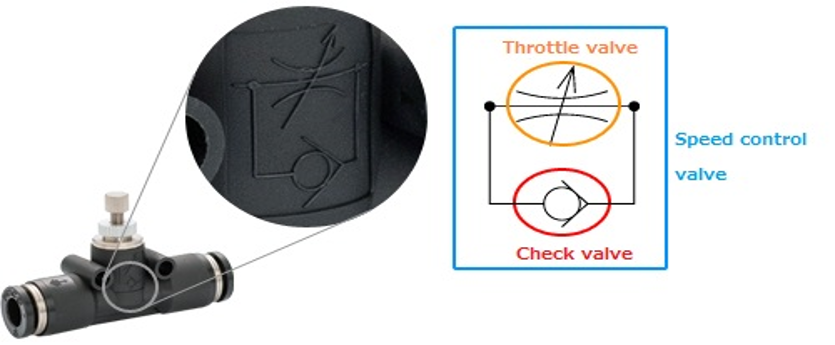
The above engraved circuit diagram indicates "Speed Controller".
To be more specific, the symbol encircled in orange is Throttle Valve (valve that throttles, adjusts air flow) and encircled in red is check valve (valve that allows air to flow in by only one direction).
Control direction is determined by the direction of check valve*.
*) Direction of free flow is from right to the left when symbol is ">", to the direction to be wider.
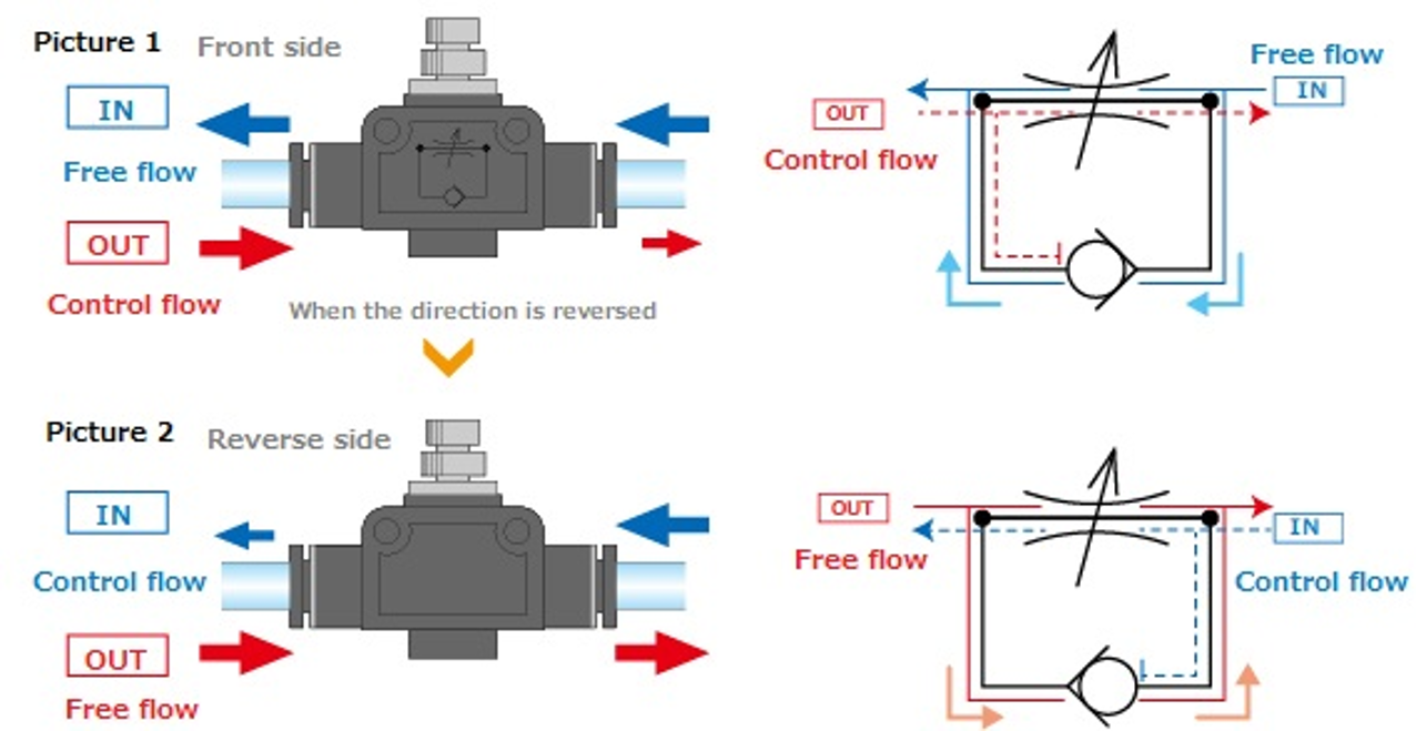
When free flow of entering air (supplying air to a cylinder) is required,
which is Meter-out control, set the direction of air and the check valve as same as Illustration 1. (Return air, which is exhausted air from the cylinder, is controlled.)
On the other hand, when free flow of coming out air from a cylinder is required,
which is meter-in control ,set the direction of air and the Check Valve as same as Illustration 2.(Entering air which is supplied to the cylinder is controlled.)
Exchange the front and back side from the position illustrated in 1, and meter-in control can be made.
The construction of Speed Controller Union Straight type is as mentioned above. Meter-in and meter-out control should be chosen according to the direction of plumbing.When installing a Speed Controller in a plumbing, make sure the direction of air flow
Low cracking pressure type is an optional specification of Speed Controller which suits for low pressure region of spring-return cylinder with the small diameter which is a kind of single acting cylinder.
Differences from the standard type are the followings:
The difference in check valve cracking pressure
Low cracking pressure type: 0.02MPa
Standard type: 0.05MPa
How to distinguish
Engraving (□K) on needle head.
*)
(AK): Meter-out Control, Low cracking pressure type
(BK): Meter-in Control, Low cracking pressure type
The spring-return cylinder
Spring-return cylinder equips spring in the cylinder body of one moving direction side.
Use the compressed air to create a driving force in one direction with pushing against the spring and return to the home position by the force of spring when exhaust compressed air. (Spring-return cylinder is typically small sized. There is inverted structure of reciprocating motion too.)
Single -acting cylinders such as spring-return cylinder, loads are added to an exhaust and influence on the motion depending on the pressure balance between working pressure at low pressure region and cracking pressure of Speed Controller. It also retard the responsiveness if piping from valve is lengthy.
Low cracking pressure type has developed to cope with these factors by making cracking pressure weak and improve responsiveness. Operating pressure range of the low cracking pressure type is restricted within 0.05 to 0.5MPa.
It can also be used for vertically movable cylinders.
However, please note that if the work piece is too heavy, the cylinder will be overloaded and adjustment will become unstable.
A Check Valve, clack valve, non-return valve or one-way valve is a valve that normally allows fluid (liquid or gas) to flow through in only one direction. In PISCO products lineup, Check Valve (with push-in fitting, etc.) is available in Control series.
Speed Controller and Throttle Valve tolerate some leakage. They don't shut off air completely. Please avoid to use these under the circumstance where leakage is not allowed at all.
Since 2-stage Speed Controller is meter-out controlled, it is not possible to control the direction in which air is applied with a single-acting cylinder.
(It is not impossible to control the speed in the return direction with a spring, etc.)
2-stage Speed Controller is not compatible with clean rooms because the exhaust method is open to the atmosphere (air is exhausted to the air as it is), but if you understand this point, clean room packaging (fluorine grease) will be available as custom-made.
To tighten Lock nut, designated way is finger tight so that the Lock Nut is knurled. There is no set appropriate tightening torque.
If a tool is used to tighten it, be careful for over-tightening which will damage a product.
Since the Slot-head Speed Controller does not have a lock function, the needle may rotate and the flow rate may change when used in a place where there is excessive vibration or impact such as strong impact from the cylinder or vibration of the device.
We conducted the following vibration tests and found no problems such as changes in flow rate.
Vibration test (reference)
Acceleration:49m/s2(5G)
Frequency: 10Hz-150Hz
Cycle: 1 oct / min (10 → 150 → 10Hz)
Number of sweeps: 5 times
Generally, the G for products transported by truck is about 3G. Imagine 5G as the maximum G level on a product when you drive on a highway.
If you are considering using it with excessive vibration more than mentioned above, use the speed controller standard with locknut.
Our "Check Valve series" are designated only for air, but "Check Valve PP for Low Operating Pressure" can flow water (fluid) as well as air. Please check the specification before actual use.
For stainless steel metal parts, there are corrosion-resistant SUS303 equivalent type and PP type (SUS304).
Inquiries about this product
It is also possible to suggest products suitable for various conditions such as applications and functions. Please feel free to contact us or visit the nearest sales office.
The following are frequently asked questions. Please check before making inquiries.
